
Understanding the True Nature of Your Injection Molded Parts
Understanding the True Nature of Your Injection Molded Parts
Design, Tooling, Process, and Material — A Holistic Case Study in When Simulation and Reality Disconnect
By Joe McFadden | Holistic Analyst | March 21, 2026
You cannot process out a bad design. You can, however, process out a good one.
That principle underpins everything that follows. Hold it in mind, because once you truly understand it, you will see it everywhere — in every failure investigation, in every design review, in every conversation between an engineer who is frustrated with the process and a process engineer who is frustrated with the design. The process is powerful. But it is not a correction fluid for decisions that should never have been made. And the design is not immune to the process that gives it life.
A Failure to Communicate
There is a famous line from Cool Hand Luke: "What we have got here is a failure to communicate." Most people remember it as a moment of power — a warden putting a prisoner in his place. But strip away the drama and you find something far more universal. Something that has played out in engineering labs, factory floors, design studios, and boardrooms for as long as human beings have built things together.
A failure to communicate is, at its core, a failure to understand. And when we fail to understand — truly understand — the nature of the systems we are working with, failure follows as surely as night follows day.
This is an essay about injection molded plastic parts. But it is also about something much bigger than that. It is about the relationship between human beings and the tools they create. It is about the seductive danger of trusting a simulation more than the evidence in front of your eyes. It is about what happens when four forces — Design, Tooling, Process, and Material — meet in the darkness of a steel mold, under enormous pressure and heat, in a fraction of a second, and how everything that results from that violent, beautiful moment is shaped by decisions made long before anyone touched a machine.
And at the center of it all, there is you. Not the software. Not the datasheet. Not the finite element model. You — the engineer, the artisan, the thinker — who must ultimately understand what no tool can fully explain.
The events at the heart of this discussion took place in 1997. The people involved may have moved on from this world. But the lessons they teach us are more relevant today than ever. Because in the decades since, we have built more powerful tools, more sophisticated simulations, more capable software — and we have not necessarily become wiser in how we use them. If anything, the opposite risk has grown. As tools become more capable and more opaque, the temptation to trust them blindly grows stronger. What follows is a gentle, persistent argument against that temptation.
The Model and the Reality
There is a particular kind of confusion that descends on an engineering team when a part fails in a place the model said it should not. The simulation said this area was fine. The stress contours were low. The safety factor looked comfortable. And yet — right there, in that exact spot that the model predicted was safe — the part cracked, fractured, or gave out entirely.
This is not a failure of the simulation tool. Not exactly. It is a failure of the model. And there is a critical difference between the two that lies at the heart of almost every product quality crisis I have witnessed across a career spanning more than four decades.
A simulation tool is a mathematical engine. Feed it the right inputs, build the right model, ask the right questions, and it will give you answers of genuine value. But the phrase — "the right inputs" — is doing an enormous amount of work. Because for a structural finite element analysis of an injection molded plastic component, the right inputs require an understanding that goes far, far beyond pulling numbers from a material datasheet.
The Ingersoll Rand Case
In 1997, Ingersoll Rand was developing a new handheld impact device — a pneumatic tool of the kind used in automotive assembly and maintenance. During product evaluation, the housings of the device were failing. Not in theory. Not in simulation. In the real world, under real loads, the housings were cracking near the opening for the trigger.
The company did the right thing — they brought in experts. The consulting firm they engaged, which I will call Company E since they are still operating, was one of the premier firms of the day. They built finite element models of the device, simulated the loading conditions, and followed best practices. And their models did not predict the failures. In fact, the regions that were failing in physical testing showed comparatively low stress in the model. There were other areas of the housing with higher predicted stress, and the engineering teams spent considerable energy studying those — while the actual failure location remained unexplained.
This kind of disconnect between model and reality is not a curiosity. It is a signal. And learning to read that signal — to understand what it is telling you about the gap between your model and the real system — is one of the most important skills an engineer can develop.
When Ingersoll Rand reached out to the Society of Plastics Engineers for recommendations, they passed along my contact information and the path to a solution began. But the solution did not come from a more powerful computer or a newer version of the software. It came from a deeper understanding of what injection molding actually does to a material, and why a glass-filled nylon part is not — cannot be — the homogeneous, direction-independent solid that the finite element model assumed it to be. That gap — between the model's assumptions and physical reality — is where almost all engineering failures live.
The Four Pillars: One Interconnected System
The performance of an injection molded part is determined by four things: Design, Tooling, Process, and Material. And here is the part most people miss — these four things are not independent of each other. They are deeply, inextricably, dynamically interdependent.
Most engineering workflows treat them as sequential stages. The designer designs. The materials engineer specifies. The toolmaker builds the mold. The process engineer sets up the machine. Hand it from one to the next, like passing a baton. And at each handoff, something critical is lost: the understanding of how each decision constrains and shapes all the others.
Think about what actually happens when you push a button and start an injection molding cycle. Plastic pellets — in this case, a glass-filled polyamide 66, a nylon reinforced with chopped glass fibers — are fed into a reciprocating screw. They are heated, sheared, melted, and accumulated in front of the screw tip. Then, in a couple of seconds, a hydraulic ram drives that melt through a small gate opening into a steel cavity machined to the precise geometry of your part. The melt enters. It flows. It cools. It freezes. A part is born.
But think about what has happened to those glass fibers during that journey. They began as oriented reinforcement within the individual pellets. Then the plastic was sheared by the rotating screw, accumulating as a non-oriented, random mass of softened material. Then the fibers were forced through a narrow gate at high velocity, flowing in a pattern dictated by the cavity geometry, the melt temperature, the steel temperature, the injection speed and pressure — all of it interacting simultaneously.
By the time the melt has frozen, those glass fibers are no longer randomly oriented. They are aligned by the shearing actions within the flow. That shear field is not uniform through the thickness, resulting in variations in the mechanisms of orientation. Because we are primarily interested in the bending performance of plastic parts, it is the outer surfaces of the part that drive structural performance. Using local flow direction is therefore a good indicator for fiber orientation in the regions that matter most.
A fiber-reinforced composite material with oriented fibers is a fundamentally different structural material than one with random fiber orientation. Its properties vary depending on direction — behavior we call anisotropic. The wooden board analogy makes this vivid: along the grain, wood is strong and stiff; across the grain, it splits easily. A well-oriented glass-filled nylon part can be nearly twice as strong in the flow direction as it is perpendicular to flow. You cannot ignore this and expect your structural model to tell you the truth.
The fiber orientation in your part — and therefore its strength and stiffness map — is not determined by the material alone. It is shaped by the design of the cavity geometry, by where the gate or gates are placed, by the temperature of the mold steel, by the injection speed profile, by the cooling channel layout, by the wall thickness transitions across the part. Change the gate location, and the flow field changes, and the fiber orientation map changes, and the structural properties of the finished part change. Every decision feeds back through the system.
Design. Tooling. Process. Material. They are one system. They always have been. Our organizational charts just pretend otherwise.
Material: What the Datasheet Doesn't Tell You
There is a ritual comfort in a material datasheet. The numbers are crisp and confident — tensile strength, flexural modulus, impact resistance — everything you need, presented in a clean table, ready to plug into your model. The problem is that these numbers are measured on carefully prepared test specimens: injection molded bars made under controlled conditions, from a single gate, with geometry designed to produce a uniform, well-oriented microstructure. They represent one point in an enormous, multi-dimensional space of possible real-world performance.
The number on the datasheet is not wrong. It is just partial. It is a sample from one corner of a much larger distribution. And when you use it as if it represents your part — your specific geometry, your specific gate location, your specific wall thickness, your specific process settings — you are making an assumption that may or may not be justified.
For the Ingersoll Rand housing, the team used datasheet properties for their glass-filled polyamide 66. Perfectly reasonable by the standards of the day. But those properties were isotropic — they assumed the material behaved the same in all directions. A glass-filled nylon part cannot behave the same in all directions. The physics of the filling process will not allow it. Near the trigger opening, the flow had taken a particular path through the cavity. The local fiber orientation at that location happened to leave the material vulnerable to the direction of the applied load. The stress was not particularly high in the global sense — but the material was not particularly strong in that local direction, either. The two facts conspired to produce a failure that the isotropic model could not see.
The Moisture Problem
The story does not end with fiber orientation. Nylon — polyamide 66 in this case — is one of the most widely used engineering thermoplastics in the world. It is strong, tough, wear-resistant, and thermally capable. It is also profoundly sensitive to moisture. Polyamide 66 is hygroscopic: it absorbs water from the atmosphere, and that absorbed water becomes part of the polymer matrix, plasticizing the chains and dramatically altering mechanical properties.
A dry specimen and a conditioned specimen of the same polyamide 66 may have tensile strengths that differ by thirty, forty, even fifty percent depending on temperature and moisture content. The impact resistance of conditioned nylon is typically much higher than dry nylon; the stiffness is lower. Which one is your part? That depends entirely on what environment it will live in — and what state it was in when it was tested or modeled.
The handling and storage of the raw material matters enormously. Was the material properly dried before molding? For polyamide 66, this typically means drying at 80°C for several hours. If residual moisture is present in the pellet when it enters the barrel, the water converts to steam at melt temperatures, producing hydrolytic degradation — a chain scission reaction that literally breaks the polymer molecules into shorter pieces and destroys toughness. The part looks identical to a good one. The mechanical properties are not.
This is why I always insist on understanding the full history that a material has experienced — from the resin manufacturer through the dryer, through the barrel, through the gate, through cooling, through post-mold conditioning, all the way to the point of loading. That history is encoded in the microstructure of the part. And the microstructure determines performance. The material speaks, if you know how to listen.
Tooling: Where All Decisions Are Tested Against Physics
Engineers often think of the mold as the end of the design process — the thing that gets built after the decisions have been made. In reality, the mold is where all your decisions are tested against physics. And physics does not negotiate. The mold is not just a cavity shaped like your part. It is a thermal system, a hydraulic system, a pressure vessel, a precision mechanism, and a material transformation device — all at once, cycling perhaps every thirty seconds, for millions of cycles over its operational lifetime.
Every decision made in mold design has consequences that propagate directly into the part. Gate location determines fill pattern. Fill pattern determines fiber orientation. Gate diameter determines shear rate in the gate, which affects fiber breakage and alignment. Runner geometry determines pressure drop, which affects how well the cavity packs during cooling.
Cooling channel layout is perhaps the most underappreciated aspect of mold tooling. The channels determine the temperature distribution within the mold steel, which determines how quickly different regions of the part cool. The cooling rate determines the degree of crystallinity in semi-crystalline materials — and polyamide 66 is semi-crystalline. The degree of crystallinity affects stiffness, yield strength, and shrinkage. Non-uniform cooling produces differential shrinkage; differential shrinkage produces residual stress and warpage.
Consider a simple box-like housing. One face has thick walls with bosses and ribs on the interior; the other is thin and relatively uniform. If the cooling channels are laid out to achieve uniform channel-to-cavity distance everywhere — ignoring the mass variation — the thin sections will freeze before the thick sections, resulting in differences in the degree of crystallinity and therefore toughness. The thick sections continue to shrink as they cool, but the already-frozen skin resists this, building in residual tensile stress. Add an impact load to that residual stress, and you have far less energy-absorbing capacity than your model predicted.
Weld Lines: The Hidden Seam
The gate location for the Ingersoll Rand housing placed the injection point in a region that produced a particular fill pattern through the trigger opening. The melt had to flow around corners, through varying wall thicknesses, past the opening geometry — and in doing so, it created weld lines. A weld line is a seam where two or more melt fronts converge. At a weld line, fibers are perpendicular to the weld rather than aligned with the primary flow, and the polymer chains have had less time and less pressure to diffuse across the interface and re-entangle. Weld line strength in glass-filled materials is typically a fraction of the parent material strength — sometimes sixty percent, sometimes far less. In impact loading, this reduction is even more severe.
Here is the deeper lesson. Tooling decisions made early in development — before a single part is molded — lock in realities that will govern every part made in that tool for its entire lifetime. The time to get these decisions right is before the steel is cut, when they cost nothing but thought and simulation and conversation. The mold does not just make parts. It makes a statement about all the knowledge — and all the assumptions — that went into its design.
Process: The Conversation That Never Ends
I have always thought of the injection molding process as a kind of conversation. The machine is speaking, constantly. It reports pressures, temperatures, speeds, cycle times, screw positions. The parts coming off the press report their own condition: their dimensions, their surface finish, their weight, their warpage. Every one of these signals is information. Most of that information is ignored.
The standard practice in many manufacturing facilities is to qualify a process — to find settings that produce parts that pass inspection — and then lock those settings in as if the goal were to never revisit them. The process is treated as something to be fixed, rather than something to be understood. But a molding process is a dynamic system. The mold heats up over the first hundred cycles of a production run. The resin lot number changes when a new shipment arrives. The ambient temperature in the facility changes with the seasons. The hydraulic fluid in the press changes viscosity as it warms up through the shift. Every one of these factors influences the actual conditions experienced by the melt, and therefore the properties of the part.
In the Ingersoll Rand case, reviewing the process settings was not just about checking injection speed and melt temperature. It meant understanding the fill pattern — how the melt was actually traveling through the cavity — and relating that to the local material properties at the failure location. The process settings, combined with the tool geometry, determined the flow field, which determined the fiber orientation map, which determined where the part was strong and where it was weak.
Consider injection speed. A faster injection typically produces higher shear rates at the gate, which can break long glass fibers and reduce reinforcing effectiveness. But a faster injection also maintains a hotter melt at the flow front, which improves weld line quality by keeping the polymer chains mobile when the fronts converge. Slower injection produces less fiber breakage but colder, weaker weld lines. There is no universally optimal injection speed — there is only the speed that is best for this part, in this tool, with this material, for this application.
The injection phase, the pack phase, the cooling phase — all of it leaves its fingerprints on the part. The residual stress state, the density distribution, the degree of crystallinity, the fiber orientation map — they are all encoded in the microstructure, invisible to the eye but present in every performance test, every fatigue cycle, every impact event the part will ever experience. To understand a part, you must understand its history. The process is not a setting to be fixed. It is a conversation to be had — every shift, every lot, every generation of the product.
The Hidden Architecture of Every Molded Part
Every injection molded part has an invisible architecture — a three-dimensional map of microstructural states that governs its performance just as surely as the nominal geometry. This architecture is not on the drawing. It is not in the mold design file. It cannot be seen with the naked eye. It exists only in the arrangement of polymer chains, crystalline domains, glass fibers, and frozen-in stress that results from the specific combination of design, tooling, process, and material that produced the part.
Skin-Core Structure
The first feature of this hidden architecture is the skin-core structure. When a polymer melt meets the cold wall of a mold cavity, it freezes almost instantly, forming a thin, rapidly quenched skin layer. This skin is typically less crystalline than the interior because the cooling was too fast to allow full crystalline development. The fibers just below the skin are strongly oriented in the flow direction, because the extensional flow at the advancing melt front stretches and aligns them. Beneath the skin is a core region that cooled more slowly, where the shear flow can actually rotate fibers toward the perpendicular direction. This alternating skin-core pattern means the part behaves like a composite laminate in the thickness direction, with properties that vary from surface to center.
Weld Lines
Weld lines form wherever two or more melt fronts converge — around holes and openings, downstream of multiple gates, at the confluence of flows that have traveled different paths through complex geometry. At a weld line, fibers tend to orient parallel to the weld interface because the converging flows push them in that direction. In unreinforced materials, weld lines may retain seventy to ninety percent of the parent material strength. In glass-filled materials, where the strength advantage comes precisely from fiber orientation along the stress direction, weld line strength can drop to forty or fifty percent of the nominal value — or lower under impact loading.
Residual Stress
The injection molding process leaves behind frozen-in stresses that result from the combination of thermal gradients during cooling and the pressure history of the packing phase. These residual stresses sum algebraically with any applied service stresses. A region with frozen-in tensile residual stress has less load-bearing capacity available before fracture than the material data would suggest. Nobody puts residual stresses on the drawing. Nobody specifies weld line location as a controlled variable — or rather, almost nobody does, and those who do are far ahead of the majority of the industry.
But here is the power in this understanding. If you know the flow physics, you can use that knowledge at the design stage — when the gate location is still a decision, when the wall thickness transitions can still be modified — to place the hidden architecture where you want it. The best injection molding engineers I have known do not just react to problems. They read the geometry of a part and, before the mold is ever designed, they can tell you where the weld lines will form, where the fiber orientation will be most anisotropic, where the sink marks are likely to appear. They are running a mental simulation. They are reading the hidden architecture before it exists. That is expertise — not a title, not a credential, but a capability built through years of deliberate engagement with the real physics of the process.
Design for Manufacture: A Genuine Collaboration
"Design for Manufacture" appears in product development frameworks everywhere. And yet, in practice, the conversation between design intent and manufacturing reality is often cursory, adversarial, or simply absent. The designer wants what the designer wants. The part has a certain geometry because that geometry serves the function. The wall is thick there because that is where the structural load is concentrated. The opening is in that location because that is where the trigger needs to be. These are legitimate design requirements — but they carry manufacturing consequences that must be understood and managed.
Take wall thickness variation. In injection molding, the flow of melt through the cavity follows the path of least resistance — it preferentially fills thick sections before thin ones. Thick sections also take longer to cool, setting the cycle time, and therefore the cost per part, and therefore the economics of the entire program. The gate location is a design decision, not a toolmaker's decision. Every designer who specifies gate location at the toolmaker's discretion is delegating a structural engineering decision to someone who may not have the information needed to make it well. The gate location determines the fill pattern. The fill pattern determines the fiber orientation distribution. The fiber orientation distribution determines the directional strength map of the part.
Draft angles, radii at transitions, the geometry of ribs and bosses — each is a design feature with manufacturing consequences. Sharp internal corners are stress concentration sites in the part, and hot spots in the mold steel where fatigue cracking can develop over time. A corner radius of even half a millimeter dramatically reduces both the stress concentration in the part and the fatigue loading on the tool. None of this means designers should become injection molding process engineers. It means that the design process should include, from its earliest stages, people who understand the manufacturing implications of design choices — not as a gate at the end, but as a genuine collaboration from the beginning.
Design intent is not just the function the part performs. It includes the process by which the part is made, because that process is co-author of the part's performance. A feature that serves the functional intent but creates a weld line in a high-stress area has a design intent that contradicts itself. Resolving that contradiction requires that the designer and the process engineer share a common language — the language of the four pillars.
And this is where that opening principle comes back with its full force. No amount of optimizing injection speed will move a weld line that the gate location has already placed in the worst possible position. No adjustment to packing pressure will correct a wall thickness transition that was always going to create differential shrinkage and residual stress. No process parameter will undo the anisotropy that flows from the geometry the designer drew. The process inherits the design. It does not override it.
But the process absolutely can destroy what a good design worked hard to achieve. A poorly controlled melt temperature, an inconsistent pack time, a dryer that was skipped — these will take a thoughtful, well-engineered design and systematically rob it of its potential. The principle cuts both ways: design with the process in mind, and run the process with respect for the design. Together, and only together, do they give you the part you intended to make.
All Models Are Wrong — But Some Are Useful
The statistician George Box wrote, in 1976, that all models are wrong, but some are useful. It is perhaps the most quoted sentence in the history of applied mathematics. And yet, despite its ubiquity, its lesson is honored more in repetition than in practice. We build models. We trust them. We forget they are models.
A finite element analysis is a model — a discretization of a continuous physical system into a finite number of elements, each with simplified material behavior, connected at nodes, solved numerically for an approximation to the actual stress and displacement fields. Every word in that sentence contains an assumption. The mesh is a discretization: coarser meshes miss stress concentrations; finer meshes approach the continuum but never reach it. The material model simplifies the actual behavior of a real material into a mathematical relationship that may or may not capture the mechanisms that matter. The loading is approximate — we often represent bolted joints as constraints, simplify distributed dynamic forces as equivalent static loads, and assume boundary conditions that are cleaner than reality.
A flow simulation — whether Moldflow, Moldex3D, or any of their equivalents — is also a model. The governing equations for polymer flow in a mold cavity are non-Newtonian, non-isothermal, compressible, viscoelastic partial differential equations that cannot be solved exactly. They can only be approximated. The quality of that approximation depends on the accuracy of the viscosity model, the thermal properties, the geometry representation, the mesh resolution, and — critically — the skill and understanding of the analyst who sets up the simulation and interprets its output.
In 1997, the flow simulation tools of the day did not include fiber orientation prediction as an integrated capability. To bridge this gap, I developed tools in Fortran that mapped the Moldflow flow direction output onto structural finite elements and used that information to assign orthotropic material properties at each element location. The gap was bridged not by waiting for a better software package, but by understanding the physics well enough to build what was needed. The resulting model was not perfect. But it was fundamentally more honest about the physics of the problem than the isotropic baseline had been.
This is the posture I want to advocate for — not the user who trusts a black-box tool, and not the skeptic who dismisses simulation as unreliable, but the artisan who understands the tool, knows its limitations, and wields it with appropriate skill and appropriate humility. The tool does not know your part. You do. Or you should.
The Mental Model: Building the Simulation in Your Brain
Long before Moldflow, long before finite element analysis, long before any of the computational tools we take for granted today, engineers built things that worked. Bridges that stood for centuries. Pressure vessels that held. Springs that cycled for millions of repetitions without failing. How? They had models — not computational models, but mental models, built up through years of experience, through careful observation, through the disciplined study of why things succeeded and why things failed. They were running simulations, but the simulation engine was the brain.
There is a moment in technical problem-solving — and if you have experienced it, you know exactly what I am describing — where you look at a situation and something speaks to you. The failure is here, not there. This is wrong, even though I cannot yet prove it. You are not guessing. You are running a mental simulation that draws on thousands of hours of accumulated pattern recognition and contextual knowledge.
When I walked into the Ingersoll Rand case and looked at the failed part, I knew the problem. Not because of any special genius, but because I had seen this kind of failure before — the fingerprints of anisotropy in a glass-filled part, the tell-tale relationship between gate location and failure site, the gap between what an isotropic model would predict and what the oriented microstructure would actually deliver. My brain had been trained on real cases, on years of hands-on work with injection molding processes, on material experiments, on failed parts examined under cross-polarized light, on flow simulations that I had not just run but coded myself — from the governing equations, in Fortran. That accumulated experience had built a mental model that was, in some respects, more sophisticated than the finite element tools available at the time — not because it could do more computation, but because it understood the physics more completely.
Building Your Own Mental Model
In 1979, when I first began working at Moldflow, we modeled the potential flow domain using what we called layflats. I would first visualize the flow within the cavity, then — often with a string and pencil — map out my predictions using very simple geometric elements: cylindrical, rectangular, circular, and radial, all two-dimensional with numerical attributes entered to account for the third dimension. All literally typed on a keyboard. I would then run the simulation and update my model based on the calculated results, adjusting based on calculated pressure drops in an iterative cycle: predict, read, correct. It sounds tedious. But it was building predictive skills that I have called upon on every project since.
This is not an old engineer ruminating about the old days — though I am certainly that. What I am saying is backed by neuroscience, and I explore it at length on my blog at www.McFaddenCAE.com. The point is not to return to typing in mesh nodes. The point is this: before you ever touch that mouse, take the time to think. Sit back. Visualize the flow within the part and cavity. Knowing that it will follow the path of least resistance, consider the geometry and the nature of the material. What areas, what features, do you see as restricting the predicted flow?
Think about it as if you are sitting in a diner at lunch. You flip over the placemat and find a maze printed on the back. Take a breath. Without using your finger, let your mind follow the paths, build your internal plan — and then, only then, act. I have been running flow simulations almost every day for over 46 years and I always begin with that internal step. Do this consistently, and you will develop the ability to seek solutions before the software has even opened.
The brain's model, like every other model, is approximate. It is limited. It is wrong in certain cases. The humility that applies to computational tools applies equally to the expert's intuition. What makes the combination powerful is precisely the combination. The mental model tells you what questions to ask. The computational tools help you quantify and verify the answers. Physical testing validates or falsifies the predictions. Each layer checks the others. None is sufficient alone.
The problem in modern engineering practice is not that we have too many powerful computational tools. The problem is that the cultivation of the mental model — the deep, embodied understanding that comes from years of hands-on engagement with the physics of real materials and real processes — is being progressively devalued. Only a human being who understands the underlying physics at a level that goes beyond clicking buttons and reading output can recognize when the tools are wrong and know what to do about it. The brain is not a legacy system to be replaced by better software. It is the irreplaceable intelligence that makes all the other tools work.
Iterative Improvement: The Engine of Engineering Progress
Every model we build — computational, mental, or organizational — is an approximation of reality. The goal is not to reach perfection, because perfection is not available. The goal is to improve: to understand the current model's limitations, identify the gaps between prediction and observation, and close those gaps, one iteration at a time.
This is how the brain works at the most fundamental level. The brain is a prediction machine. It builds models of the world, uses those models to generate predictions, and continuously updates them based on the discrepancy between prediction and observation. When what we see confirms what we expected, the model is strengthened. When what we see surprises us, the brain is forced to update. This process is called learning. It is exactly the same process by which good engineering knowledge advances.
Starting at the end of the 1970s, engineers had, for the first time, a quantitative basis for comparing gate locations and process conditions before building a tool. Over the following decades, the models improved. Three-dimensional solid mesh models replaced midplane approximations. Fiber orientation prediction was integrated. Residual stress calculation was added. Crystallization kinetics models were implemented. Each improvement came from the same cycle: observe a discrepancy between model prediction and physical reality, understand the physical mechanism responsible, implement a more accurate mathematical representation of that mechanism.
But here is what every one of those improvement cycles required: human beings who understood both the physics and the modeling well enough to recognize the discrepancy, diagnose its cause, and implement the improvement. The model improved because people improved. This is the mindset I want to encourage — not reverence for the tool, and not dismissal of the tool, but a dynamic, iterative engagement with it. Use it. Trust it where it has been validated. Question it where its assumptions may not hold. Test its predictions against reality. And when you find a discrepancy, treat that discrepancy not as a failure of the tool, but as an invitation to understand the physics more deeply.
The engineering teams who solved the world's hardest problems were not the ones with the most powerful software. They were the ones with the most rigorous intellectual process. They asked what assumptions their models were making. They designed experiments to test those assumptions. They built better models when the old ones were insufficient. They documented what they learned. They taught it to the next generation. That process — iterative, humble, rigorous, and deeply engaged with physical reality — is the engine of engineering progress. It always has been, and no amount of computing power changes that.
You Are the Critical Factor
I want to return to the Ingersoll Rand story one final time — not to revisit the technical details, but to think about what it says about the role of the engineer. Company E followed best practices. They built a finite element model, applied load cases, and reported stress distributions. Their work was competent. It was also, in the end, insufficient — not because they were incompetent, but because the model they built did not represent the physical reality of the part they were analyzing. They did not know what they did not know.
I was brought in not because I had access to better software. I did not. I was brought in because I understood something they had not accounted for: that an injection molded glass-filled nylon part is not a homogeneous, direction-independent solid, and that treating it as one was the root cause of the disconnect between their model and reality. That understanding was not in any software package. It was built up through years of working with real parts, real processes, real failures.
This is what I mean when I say: you are the important factor. Not in a motivational-poster sense, but in a precise technical sense. The quality of the model — any model — is determined by the understanding of the person who builds it. The insight that resolves a quality crisis is, at its root, an act of human intelligence applied with appropriate context and depth.
The tools are powerful, and they are getting more powerful every year. Today's integrated simulation environments can predict fiber orientation, residual stress, warpage, and structural performance in a single workflow that would have taken months of custom coding in 1997. That is genuinely remarkable and genuinely useful. But the tools have not become wiser. They have not learned to question their own assumptions. They do not know when their material model is inadequate, or when the mesh is too coarse to capture the stress gradient at the failure location, or when the loading assumption does not reflect reality. They compute what they are told to compute. They assume what they are told to assume.
You are the one who decides what to compute. You are the one who decides what to assume. You are the one who looks at the output and decides whether to believe it. And to do that well, you need to understand the physics deeply enough to know when the output is telling you the truth and when it is telling you a sophisticated lie. That depth of understanding is not something any tool can give you. It comes from engagement — from curiosity, from deliberate practice, from the willingness to build your own models from the governing equations when the commercial packages do not do what you need.
The tools will keep improving. They will keep getting faster, more integrated, more capable. But the engineer who understands — who can question the tool, improve the model, read the physics in the failure surface — that engineer is not obsolete. That engineer is more valuable than ever. Because as the tools become more powerful and more opaque, the need for human intelligence that can see through them, and beyond them, only grows.
Conclusion: Never Mistake the Map for the Territory
We have traveled a long way from a cracked housing on a pneumatic impact wrench. We have been through the physics of polymer flow and fiber orientation, through the hidden architecture of weld lines and residual stress, through the relationship between tooling design and part performance, through the philosophy of models and their limitations, through the nature of expertise and what it actually means to understand something deeply. And we arrive back where we began: with a failure to communicate.
Product quality failures — real product quality failures, the ones that damage brands and injure people and cost companies enormous sums to remedy — almost never have a single technical cause. They have a systems cause. They happen when the knowledge that would have prevented the failure existed somewhere in the organization — in the materials engineer's understanding of moisture sensitivity, in the process engineer's awareness of a troublesome weld line, in the toolmaker's concern about cooling uniformity — but that knowledge never reached the people who needed it, when they needed it.
The four pillars are not just technical domains. They are communities of knowledge. And the people in those communities need to talk to each other — not just at design reviews and failure investigation meetings, but continuously, at the working level, in the language of shared physical understanding. None of us needs to be an expert in all four areas. We need to be literate — to understand the language and the basic concepts well enough to have productive conversations across the boundaries.
The goal is not to trust the tool. The goal is to be worthy of trusting your own judgment. And to earn that trust, the same way it has always been earned: by doing the work. By learning from failures — your own and others'. By developing, day by day, a brain that simulates better than it did the day before. You are the driver. The tools are yours. Understand them. Question them. Improve them. And never, ever mistake the map for the territory.
Joe McFadden
Holistic Analyst | Engineer | Lifelong Learner
Combating engineering mind blindness, one student at a time.

From Furnace to Finished Casting — The Designer's Journey
Part One — From Furnace to Finished Casting: The Designer's Journey
Most design guidelines tell you what to do. This guide explains why — and what actually happens to your part when you get it wrong. Part One of the High Pressure Die Casting series takes engineers who design die cast parts through the complete production journey, from the moment metal is melted in the furnace to the moment the casting is ejected from the die. Along the way it covers the difference between cold and hot chamber machines, what aluminum, zinc, and magnesium each demand from the designer, and how decisions about wall thickness, draft angle, ribs, and section changes play out in milliseconds of metal fill. Part of the Combating Engineering Mindblindness series.
Part 1 Audiobook link → https://www.dropbox.com/scl/fi/zdfj585z22aovmq0lypmq/Designer_Journey_HPDC_part1_McFadden_7May2026.mp3?rlkey=809ypvtftrfai7bhijsnbt922&st=8cl697jj&dl=0
COMBATING ENGINEERING MINDBLINDNESS SERIES
HIGH PRESSURE
DIE CASTING
What Every Designer Needs to Know
PART ONE
From Furnace to Finished Casting — The Designer's Journey
Joseph P. McFadden Sr.
Engineering Fellow, Zebra Technologies
Adjunct Professor of Mechanical Engineering, Fairfield University
Collaboratively developed with Claude · May 2026
mcfadden@snet.net · www.MCFADDENCAE.com
Engineering mindblindness is what happens when an engineer knows their discipline deeply but cannot see — or has never been shown — how their decisions ripple through the systems around them. The designer who has never stood on a production floor. The process engineer who has never read a stress analysis. The quality engineer who does not understand the metallurgy of what they are inspecting.
Each of these engineers is highly competent in their own domain. And each, without realizing it, is missing something that would make them dramatically more effective.
This series exists to close those gaps. Not by turning designers into tooling engineers or process engineers into metallurgists — but by giving each discipline enough visibility into the others that they can see the connections. Because the connections are where failures hide.
Every failure tells a story.
That is my tagline. And the story I hear most often — the one that frustrates me more than any other — is the one where a part fails not because the engineering was wrong, but because the person who designed it had no idea what was going to happen to it after they released the drawing.
I have spent over forty years in die casting. As employee number three at Moldflow North America, I helped build some of the first commercial simulation software for this process back in the early 1980s. I teach Fracture Mechanics at Fairfield University. I serve as Engineering Fellow at Zebra Technologies. And I have seen, over and over again, smart engineers design parts that were beautiful on paper and deeply problematic in production — not because they were bad engineers, but because nobody ever told them what actually happens inside a die casting machine.
This guide is for you. If you have designed parts that get die cast, or if you are about to, and you have relied on a design guidelines checklist without really understanding why those guidelines exist — this is for you. We are going to fix that.
WHO WE ARE AND HOW WE WILL PERFORM DEPENDS ON OUR PAST
Before we get into the process, I want to give you a mental model that will change how you think about die casting forever.
Think about this: who we are — how we think, how we respond under pressure, what we can endure and what will break us — depends upon our past. Our lived experience. Every formative moment, every stress we carried, every environment that shaped us — all of it is present in who we are today.
The same is true of your die castings.
Every part that comes off a die casting machine carries its entire history inside it. The temperature the metal was when it was poured. The speed at which it was pushed through the gate. The pressure that was applied as it solidified. The stresses that locked in as it cooled. That history is invisible to the naked eye — you cannot see it in a dimensional inspection, you cannot feel it with your fingers — but it is there. And it determines how the part will behave in service.
Understanding the complete journey of your part — from raw metal to finished casting — is not optional background knowledge. It is the foundation of good design.
WHAT IS DIE CASTING AND WHY SHOULD YOU CARE
Let me start with what die casting actually is, because the name does not tell you much.
Die casting is a manufacturing process in which molten metal is forced, under very high pressure, into a precision steel mold called a die. The die is a mirror image of the part you want to make — a negative carved in hardened tool steel, able to withstand hundreds of thousands of injection cycles. The metal fills the die cavity in a fraction of a second, solidifies almost immediately against the cold steel walls, and is then ejected as a finished part.
Think about that for a moment. A complex, thin-walled, dimensionally accurate metal part — produced in somewhere between thirty seconds and two minutes per cycle, day after day, at volumes that no other metal process can match.
Compare that to machining, where you start with a block of metal and remove everything that is not the part. Machining is extraordinarily precise, but it is slow and expensive, and it wastes a great deal of material.
Compare it to sand casting, where the mold is made of sand, used once, and broken away to release the part. Sand casting can make very large, complex shapes, but tolerances are loose, surface finish is rough, and cycle times are long.
Die casting sits in a different space entirely. High volume. Tight tolerances. Good surface finish. Thin walls. Consistent dimensions cycle after cycle. And here is the critical thing for you as a designer: almost everything about what die casting can and cannot do for your part is determined by choices you make before manufacturing begins.
COLD CHAMBER AND HOT CHAMBER — WHAT IS THE DIFFERENCE
There are two main types of die casting machines, and the distinction matters for what your part can be made from.
In a hot chamber machine, the injection system — the mechanism that forces the metal into the die — is actually submerged in the molten metal. The metal is always there, always ready. When a shot is needed, a plunger pushes metal directly from the molten bath, through a gooseneck passage, and into the die. Because the system is always hot and primed, cycle times are fast and the process is very efficient. Hot chamber machines are used for low-melting-point alloys: zinc, tin, and lead-based alloys. Zinc is by far the most common.
In a cold chamber machine, the injection system is completely separate from the furnace. For each shot, a measured amount of molten metal is transferred — by hand ladle or robotic arm — from the furnace into a steel cylinder called the shot sleeve. A hydraulic plunger then pushes that metal out of the sleeve and into the die. Cold chamber is essential for aluminum — aluminum's melting point and reactivity would attack and corrode the submerged components of a standard hot chamber system. So aluminum is always cold chamber.
Magnesium is more nuanced — and this is a point that gets oversimplified in a lot of literature. When shot size is appropriate, magnesium is actually best processed in hot chamber. Here is why: magnesium solidifies extremely quickly, and it is highly sensitive to oxide formation from air contact. The hot chamber process keeps the melt sealed in a protected steel crucible under cover gas — typically sulfur hexafluoride or modern substitutes — which directly limits that oxide exposure. The shorter transfer path also works in magnesium's favor given its rapid solidification. Hot chamber magnesium runs twenty-five to forty percent faster than cold chamber and generates significantly less recyclable scrap.
When cold chamber is used for magnesium — for larger parts where shot size demands it — the shot sleeve cannot simply be left as-is. Magnesium loses heat so fast that a standard cold chamber sleeve would cause the metal to begin solidifying before injection completes. The correct approach is a modified hybrid system: the shot sleeve is fitted with insulation and heaters to maintain metal temperature through the transfer and injection sequence.
But I want to be direct about this: the hybrid is a compromise. It is an engineering workaround, not a solution. Every time you add insulation and heaters to a cold chamber sleeve to manage magnesium's thermal behavior, you are compensating for a fundamental mismatch between the process and the material. I have spent considerable time troubleshooting these systems, and my preference — based on that experience — is hot chamber unless there is genuinely no other option.
Here is something every designer needs to understand — whether you are working with magnesium in a hybrid cold chamber or any other alloy and process combination: shot ratio is critical, and it directly affects the quality of the part you will receive.
Shot ratio is the relationship between the volume of metal you are injecting and the total volume capacity of the shot sleeve. Too low a ratio — meaning your part is small relative to the sleeve — and the metal sits in that sleeve too long before injection. It loses temperature. It picks up contamination. It begins to develop a skin of partially solidified metal and oxide film along the sleeve walls. When the plunger advances, that degraded metal at the front of the shot does not stay in the overflow wells where it belongs — it gets pushed ahead into your cavity.
That contaminated leading metal — carrying solidified particles, oxide films, and cold laps — enters your part and gets locked into the microstructure during solidification. And here is why this matters to you as a designer: those oxide films and solidified particles are not just cosmetic problems. They are stress concentrations. They are crack initiation sites under fatigue loading. They are the points where a part that should have lasted millions of cycles fails at a hundred thousand. They are the kind of defect that surfaces in a failure analysis and gets blamed on the wrong cause — because the part looks fine externally, the dimensions check out, and nothing in the inspection record flagged it.
The die can be perfectly designed. The gating system can be textbook correct. The part can still fail — because the condition of the melt in the sleeve before injection was poor, and nobody treated that as a quality variable.
This is the holistic point. Process condition upstream of the die is as important as the die design itself. As a designer, you cannot control shot ratio directly — that is a process and tooling decision. But you can design parts whose volume is appropriate for the machine being specified, flag shot ratio as a critical process parameter when working with magnesium in a hybrid cold chamber system, and ask the right questions of your foundry partner before you release the drawing. A well-designed part on the wrong machine with the wrong shot ratio will underperform. Every time.
The simple rule: aluminum is always cold chamber. Zinc is almost always hot chamber. Magnesium goes hot chamber when shot size permits — and requires a carefully managed hybrid cold chamber when it does not, with shot ratio treated as a primary quality parameter. Most structural parts, enclosures, and brackets in industry are aluminum. Most small precision parts, connectors, and decorative hardware are zinc. Magnesium shows up where weight is critical — portable devices, automotive components, aerospace.
THE THREE METALS — WHAT THEY MEAN FOR YOUR DESIGN
Let me introduce you to the three main die casting metals, because your choice — or your customer's choice — of material is not just a strength and weight decision. It determines what the process can do, what failure modes you need to worry about, and what surface treatments are available.
Aluminum. This is the workhorse of die casting. Alloys like A380 and ADC12 offer good strength, light weight, excellent thermal and electrical conductivity, and decent corrosion resistance. Most structural die castings — automotive brackets, electronic housings, power tool bodies — are aluminum. The cold chamber process used for aluminum produces excellent surface finish and tight tolerances. The catch — and this is important for designers — aluminum die castings have a known vulnerability to hydrogen embrittlement during electroplating processes. We will talk about that later.
Zinc. Zinc is denser than aluminum but has remarkable properties that make it the material of choice for small, intricate, thin-walled parts. Zinc can be die cast to wall thicknesses that would be impossible in aluminum — sometimes less than half a millimeter. It accepts plating beautifully. It has very low melting temperature, which means dies last longer and cycle times are faster. If you are designing a small housing, a connector body, a decorative badge, or a precision mechanism, zinc deserves serious consideration.
Magnesium. The lightest structural metal available. Magnesium is roughly thirty percent lighter than aluminum and significantly lighter than zinc. For portable devices — laptops, cameras, hand-held scanners — where every gram matters, magnesium can be the right answer. But magnesium requires surface protection. It is highly reactive, and without proper coating or plating, it will corrode. And like aluminum under the wrong conditions, it can be vulnerable to stress corrosion cracking.
Each of these metals has its own personality on the production floor. Each responds differently to injection speed, pressure, and temperature. Each demands different thinking from the designer.
THE JOURNEY YOUR PART TAKES — FROM FURNACE TO YOUR HANDS
Now let me take you through the actual production process. Not as an abstract description — but as a story that connects every step to decisions you made on your drawing. Because that connection is real, and most designers never see it.
THE FURNACE
Your part starts as ingots. Solid blocks of the alloy you specified — stacked in a holding furnace and melted down to a liquid bath. For aluminum, that means temperatures around twelve hundred degrees Fahrenheit. For zinc, considerably lower — around eight hundred degrees. For magnesium, somewhere in between.
The surface of the melt looks deceptively calm — like a glowing, metallic lake. But beneath it, chemistry is happening. Aluminum is hungry for hydrogen. Any moisture in the air, on the tools, on the ingot surface — at temperature, that moisture breaks down and hydrogen goes directly into solution in the liquid metal. Dissolved hydrogen is one of the leading causes of porosity in finished castings.
This is why good foundries degas their melt — introducing inert gas through a spinning lance to pull hydrogen out before it ever enters your part.
Why does this matter to you as a designer? Because your wall thickness and part geometry determine how quickly the metal solidifies, which determines how much time that dissolved hydrogen has to escape versus getting trapped as a void. Thick walls are slower to solidify. Slower solidification means more time for gas to migrate and coalesce into porosity. Thick walls and die casting are a problematic combination — and that is a design decision, not a production decision.
THE SHOT SLEEVE — WHERE THE CLOCK STARTS
A measured amount of molten metal — exactly calculated for your part's volume plus the runner system and overflows — is transferred into the cold chamber shot sleeve. The moment that liquid aluminum touches the cold steel of the sleeve, it begins losing temperature. The clock has started. Everything from here to the completed casting has to happen before the metal decides it wants to be solid.
Your part geometry determines how much metal is needed. Your wall thickness determines how much time the metal has. Your overall part volume relative to the machine's capability determines whether this operation is even feasible on a given machine.
DIE LUBRICATION — WHY YOUR PART NEEDS A RELEASE AGENT
Before the metal is injected, the die is sprayed with a water-based lubricant. This does three things simultaneously: it lubricates the surface so the casting will release without tearing, it cools the die steel to maintain the right operating temperature, and it creates a thin thermal barrier that keeps the metal fluid long enough to fill thin sections.
Here is where your design connects: the lubricant needs to coat every surface of the cavity evenly, and the excess needs to be blown off with compressed air. Any pooling of lubricant in deep pockets, sharp corners, or areas the air jet cannot reach creates a gas source. When the hot metal arrives, that pooled lubricant vaporizes. Those vapors have nowhere to go — they become porosity in your part.
Deep pockets in your design — think of blind holes, deep bosses, enclosed corners — are difficult to spray and blow off cleanly. The lubricant traps. The gas forms. The porosity appears. Every time.
SLOW SHOT AND FAST SHOT — THE TWO PHASES OF INJECTION
Now the die is closed under enormous clamping force — hundreds or even thousands of tons, depending on the machine and the part — and injection begins.
It happens in two distinct phases, and both matter to your part.
The first phase is called the slow shot. The plunger begins to move slowly — deliberately — pushing the metal forward through the shot sleeve. The metal only fills about half the sleeve diameter, with air above it. Move too fast and the metal surface breaks into a wave that folds air into the melt. That entrained air becomes porosity in your casting. The slow shot velocity is carefully controlled to advance the metal as a calm, coherent front — no waves, no tumbling, no folding.
Then, at a precisely calculated position, the machine switches to fast shot. The hydraulic accumulator releases its stored energy. The plunger accelerates. And the metal drives through the gate system at velocities often exceeding thirty to forty meters per second — roughly seventy to ninety miles per hour at the gate.
In milliseconds, your part cavity must fill completely.
Why does your design affect this? Because the path the metal takes through your cavity — determined by your wall thicknesses, your rib locations, your boss placements — either helps or fights that fill. Metal travels toward the thinnest sections last. It takes the path of least resistance first. If your design has widely varying wall thicknesses, the metal will race through the thick sections and struggle to reach the thin ones before freezing.
Uniform wall thickness is one of the most important design principles in die casting. Not because the guidelines say so — but because of the physics of what happens in those milliseconds of fill.
WHERE YOUR PART IS ACTUALLY MADE — THE GATE AND CAVITY
The metal does not flow directly from the shot sleeve into your part. It travels first through a feed system — a network of channels called runners — and then through a critical restriction called the gate, or ingate, before entering the cavity that is the negative shape of your part.
The gate is the narrowest point in the entire flow path. Its size, shape, and location are chosen by the tooling engineer to control the velocity and direction of metal entering your part.
Here is what you need to understand as a designer: where that gate is located on your part determines where the hottest, fastest metal arrives first. It determines where weld lines form — those areas where two flow fronts meet and must fuse. It determines where porosity is most likely to concentrate. And it leaves a mark on the part after the gate is removed.
Gate location is a tooling decision, but it is constrained by your design. The parting line — where the two halves of the die meet — is determined by your geometry. The available surfaces for gate placement are determined by your geometry. When you design a part without thinking about where the die will open and where the gate will go, you often force the toolmaker into compromises that hurt part quality.
INTENSIFICATION — THE PRESSURE THAT FIGHTS SHRINKAGE
After the cavity fills, the machine does one more thing that most designers have never heard of: it applies intensification pressure. A secondary hydraulic system drives the plunger forward with additional force, packing more metal into the cavity under very high pressure — sometimes tens of thousands of pounds per square inch.
Why? Because metal shrinks as it solidifies. Aluminum loses roughly six percent of its volume going from liquid to solid. That volume has to come from somewhere. If the gate is still open and the machine is applying intensification pressure, additional metal flows in to feed that shrinkage. If the gate is not open — or if your wall design does not allow pressure to transmit through the part — the shrinkage becomes porosity in the thick sections.
This is why die casting guidelines tell you to avoid thick sections. It is not just about fill time — it is about the impossibility of feeding shrinkage through a part that has already frozen solid around its perimeter while the core is still liquid.
SOLIDIFICATION — WHERE STRESSES ARE BORN
The metal solidifies from the outside in. The surface of your part — in contact with the cold steel die — freezes first, in milliseconds, forming a fine-grained skin. The interior freezes more slowly.
This creates a residual stress state that is locked into every die casting ever made: the surface is in compression, the core is in tension. Under normal service conditions this is manageable. But add a plating process — with its acid cleaning steps, its electrochemical reactions — and that tension in the core combines with hydrogen that diffuses in from the plating bath, and you have the conditions for delayed fracture. A part that passed every inspection, failed in the field.
I have written an entire separate guide on that subject — Die Casting Metallurgy — because it is one of the most misunderstood failure modes in the industry. For now, the point is this: your part arrives at your hands already carrying internal stresses. Your design choices during its formation in the die determine whether those stresses are manageable or dangerous.
EJECTION — WHY DRAFT ANGLES ARE NOT OPTIONAL
When the casting has solidified sufficiently, the die opens and ejector pins push the part off the die surface. This is where one of the most basic die casting design rules becomes viscerally clear.
Draft angle.
Draft is a slight taper on all vertical surfaces — surfaces parallel to the direction the die opens. Without draft, the part grips the die steel as it tries to release. The ejector pins push harder. The part distorts, tears, or fractures. The die surface wears prematurely.
One to two degrees of draft on internal surfaces, one to three degrees on external surfaces, is the standard guideline. But I want you to understand why, not just what. The die is pulling away from the part as it opens. Any surface that is perfectly parallel to that direction of travel has nothing to help it release. Taper gives it a way to slip free smoothly. Without it, you are asking the part to peel away from a surface it is simultaneously contracting onto as it cools.
Every time a designer sends me a part with zero-draft walls and says "can we make an exception," I ask them to imagine trying to pull a perfectly tight-fitting metal sleeve off a perfectly cylindrical steel post. Now imagine doing that half a million times. That is what you are asking the tool to do.
SHAKE OUT — AND WHAT YOU GET BACK
After ejection, the part is still attached to the runner system — the channels of metal that fed it — and to small reservoirs called overflows, which collected the first, coldest, most contaminated metal that entered the cavity. All of that gets trimmed away, either in a trim die or by tumbling, leaving behind the finished casting with its gate mark or marks.
That gate mark location — where the metal entered your part — will be visible. It can be minimized but not eliminated without secondary machining. If your part has a surface that is cosmetically critical and visible in the final assembly, that surface needs to be protected from the gate location.
The runner system and overflows go back to the furnace as returns. The casting goes to inspection, secondary operations if any, and then surface treatment.
THE DESIGN PRINCIPLES THAT COME FROM ALL OF THIS
Now that you have walked through the process, I want to give you the design principles — not as a list to memorize but as conclusions that follow logically from what you just heard.
Uniform wall thickness. The single most important die casting design principle. Not because it is on every guidelines sheet, but because of the physics of fill time, solidification, and intensification. Abrupt changes in wall thickness create areas where the metal races through one section and struggles to reach another. They create solidification hot spots where shrinkage porosity concentrates. They create stress risers. The target for most die cast alloys is one and a half to three millimeters for aluminum, with thinner possible in zinc. Transitions between sections should be gradual — tapered over a distance of at least three times the wall thickness change.
Draft angles on all vertical surfaces. You now understand why. One degree minimum, more on textured surfaces. External surfaces can sometimes get away with less than internal. Cores — features that project into the cavity — need more draft because they heat up more and the casting contracts onto them.
Avoid undercuts wherever possible. An undercut is any feature that would prevent the part from ejecting in the direction the die opens. Think of a hook, a side hole, or a groove that runs parallel to the parting surface. Undercuts require side actions — moving sections of the die that retract before the main die opens. They add cost, add complexity, add potential leak paths, and reduce die life. If your design has a feature that is only there for aesthetic reasons and it requires a side action, challenge it.
Ribs instead of thick walls. If you need stiffness, ribs are the die caster's friend. A rib that is sixty to seventy percent of the adjacent wall thickness, with proper draft, gives you stiffness without creating a solidification hot spot. Thick sections trap liquid metal in their cores while the perimeter freezes — the shrinkage has nowhere to go. A properly designed rib avoids this entirely.
Generous radii on all internal corners. Sharp internal corners are stress concentrators in the part and stress concentrators in the die steel. The die steel at a sharp corner will fatigue and crack over time, creating fins and tears in the casting. A minimum radius of half the wall thickness on internal corners is the standard, and more is better.
Boss design. Bosses — cylindrical protrusions for screws or inserts — are common in die castings. The problem is they are often thick sections sitting on thinner walls. The correct approach: the boss wall should be about seventy percent of the adjacent wall thickness. Support it with ribs if structural load is applied. And consider that the thread in a die cast boss is often formed by a tapping operation, not by the casting itself — the cast material is soft enough that a self-tapping screw may work, but structural loading requires an insert.
Parting line awareness. The parting line is where the two halves of the die meet. It appears as a line or slight step on your part. You cannot eliminate it — it is a fundamental consequence of the process. But you can design your part so the parting line falls in an unobtrusive location, does not interfere with sealing surfaces or mating features, and does not cross a cosmetically critical area. The parting line location follows from the geometry of your part. Design the geometry with the parting line in mind.
A WORD ABOUT TOLERANCES
Die casting is a precise process, but it is not machining.
As-cast dimensional tolerances for aluminum are typically plus or minus point two to point three millimeters for features within one die half, and somewhat looser for features that cross the parting line or involve moving die components. These are general guidelines — actual achievable tolerances depend on the size of the part, the tool design, and the process control of the specific foundry.
If your design requires tighter tolerances than the casting process can reliably hold — for a sealing surface, a bearing bore, a precision mounting feature — those features should be called out for secondary machining. A die cast part with a machined bore is a very common and entirely practical solution. Designing as if the casting process can hit machined tolerances across the whole part is a recipe for high scrap rates and production problems.
Think of the casting as a near-net-shape preform. It gives you the overall geometry. Secondary operations give you the critical dimensions. Knowing which is which before you release the drawing saves enormous pain later.
WHERE WE GO FROM HERE
In Part Two, we are going to go deeper into the gating system — the design of the runners and gates that deliver metal to your part — and into the surface treatment decisions that follow casting. Because those surface treatments are not just cosmetic decisions. They interact with the microstructure of the casting in ways that can cause failure months after the part was made, under conditions that should be nowhere near the breaking point.
Every decision you make as a designer — wall thickness, surface finish call-out, plating specification, draft angle, rib geometry — connects to what happens on the production floor and in the field. That connection is real. Understanding it is the difference between a designer who calls the foundry with problems and a designer who prevents them.
That is what Part Two is about.

Part 1
Part 1 — The Complete Journey We start at the furnace, not the gate. Because the part carries its history. Hydrogen absorbed in the melt. Air entrained in a rushed slow shot. Residual stress locked in during solidification. All of it shows up later — usually at the worst possible moment. We walk through furnace practice, machine architecture, shot ratio, die spray, plunger lubrication, slow shot, fast shot, intensification, and solidification. The goal is understanding why each step matters, not just memorizing the settings.
Part 1 Audiobook link → https://www.dropbox.com/scl/fi/krhnycrk65tyvopuc6ild/Pro_Version_Part_1_Journey_HPDC_Journey_8_May2026.mp3?rlkey=2533oa1edaoqcvzlaewbr4hd2&st=rse5zvoe&dl=0
HIGH PRESSURE DIE CASTING
HPDC Gating: A Holistic Journey
PART ONE · PROFESSIONAL EDITION
Machine Architecture · Process Fundamentals · Fill Dynamics · Lubrication
Joseph P. McFadden Sr.
Engineering Fellow, Zebra Technologies
Adjunct Professor of Mechanical Engineering, Fairfield University
44+ Years · Manufacturing Simulation & Failure Analysis
Collaboratively developed with Claude · May 2026
mcfadden@snet.net · www.MCFADDENCAE.com
Think about this for a moment.
Who we are — how we think, how we respond under pressure, what we can endure and what will break us — depends upon our past. Our lived experience. Every formative moment, every stress we carried, every environment that shaped us — all of it is present in who we are today.
The same is true of your die castings.
How a part will perform in service — whether it will hold together under load, survive a plating process, resist corrosion, or fracture without warning — is not determined at final inspection. It was determined in the furnace. In the shot sleeve. At the gate. During solidification. The part carries all of it. Written into the microstructure. Invisible to the eye, but present nonetheless.
A part that grew up under stress — entrained air from a rushed slow shot, hydrogen absorbed from a poorly managed melt, residual tension locked into the core because the wall was too thick and the cooling too far away — that part may look perfect. It may pass every inspection. But put it under load, expose it to the wrong environment, and what was hidden comes out.
Understanding the complete journey is not optional. It is the whole point.
This is the holistic approach. And it is where we begin.
WHY THIS WORK MATTERS TO ME
Every failure tells a story.
That is my tagline. And I mean it. I have spent decades doing failure investigations — picking up broken parts, looking at fracture surfaces under a microscope, tracing a crack back through the microstructure to the moment it began. There is something deeply satisfying about that work. The part failed. Someone needs to know why. And I get to be the one who figures it out.
In a way, a failure investigation is a grim tale with a rewrite. The part broke — that is the grim part. But the investigation finds the root cause, names it, and gives someone the knowledge to prevent the next one. That is the rewrite. The happy ending.
But here is the truth.
I would rather never get that call.
I would rather the part never broke. I would rather the engineer who designed the gating system understood — from the beginning — why wall thickness and gate thickness and intensification pressure are not independent choices. I would rather the process engineer who set the slow shot velocity understood exactly what they were preventing when they got that number right. I would rather the quality engineer reviewing that first article inspection understood that the surface looks fine but the story inside the microstructure is what actually matters.
Failure investigations are reactive. Something has already gone wrong. Someone has already been hurt — financially, reputationally, sometimes physically. The investigation closes the loop, but it cannot undo the damage.
What I actually prefer — what drives the work that goes into guides like this one — is helping write the positive story from the start.
Understanding the complete journey. Designing the gating system that gives the metal the best possible path. Managing the process so the part that comes off the machine carries the right history inside it. Not a history of compromises and near-misses, but a history of decisions made with full understanding of why they matter.
Every failure tells a story. But every well-made part tells one too. I know which story I would rather help you write.
Before we talk about gates and runners and PQ squared analysis, I want to take you somewhere first.
I want you to stand on the floor of a die casting cell. Not in the design office. Not in front of a simulation screen. On the floor. Where the heat is real and the metal is moving.
Because everything we talk about in this guide — every calculation, every design principle, every decision about gate thickness and runner geometry — traces back to this place. This process. This journey.
Let me walk you through it. All of it. Start to finish.
THE FURNACE
It starts with ingots.
Solid blocks of aluminum — or zinc, or magnesium — stacked and waiting. Each ingot is a precise alloy specification. A380 aluminum, perhaps. Zamak 3 zinc. AZ91D magnesium. The alloy choice was made long before the ingot arrived at this furnace, and it drives every process parameter that follows.
Those ingots go into the holding furnace. For aluminum, we are talking about temperatures in the range of eleven hundred to fourteen hundred degrees Fahrenheit — roughly six hundred to seven hundred and sixty degrees Celsius. The metal melts. It transforms from a solid block into a glowing, liquid bath that looks almost deceptively calm from the surface. The surface looks deceptively calm — like a glowing lake. But beneath it, hydrogen is dissolving from every trace of moisture on the ingot surface, the ladle, the tools.
But calm is not the right word for what is happening inside that melt.
Aluminum is hungry for hydrogen. Moisture in the air, moisture on the ingot surface, moisture from the tools and ladles — at temperature, that moisture breaks down and the hydrogen goes directly into solution in the liquid metal. Every part per hundred thousand of dissolved hydrogen in that melt is a potential void waiting to form when the metal solidifies.
This is why proper furnace practice matters before the metal ever touches the die.
Good operations degas the melt. A rotary degassing lance introduces nitrogen or argon — sometimes a small fraction of chlorine — into the bottom of the melt through a spinning impeller. The gas bubbles rise through the aluminum, and dissolved hydrogen attaches to those bubbles and rides them to the surface. The dross — that gray, oxidized skin that forms on top — gets skimmed off.
Temperature is monitored continuously. Too hot and you are dissolving more hydrogen, burning off alloying elements, degrading the melt. Too cold and viscosity increases, fluidity drops, and you will struggle to fill thin sections. The furnace operator is managing chemistry and physics simultaneously, even if they do not think of it in those terms.
COLD CHAMBER, HOT CHAMBER, AND THE HYBRID — WHAT YOUR MACHINE TYPE MEANS FOR THE PROCESS
Before we follow the metal from the furnace into the shot sleeve, I want to address something that I find gets surprisingly little attention among tooling engineers. You know the tooling. You know how the die is built and how it functions. But the machine the die goes into — and the process implications of that machine type — are often less well understood than they should be. And that gap shows up in the quality of the parts that come off your tooling.
There are two fundamental machine architectures in die casting: cold chamber and hot chamber. The choice is driven by the alloy. But the process implications run much deeper than most tooling people appreciate.
In a cold chamber machine, the injection system is external to the furnace. A measured amount of molten metal is transferred — by hand ladle or robotic dosing arm — from the holding furnace into the shot sleeve for each individual shot. The sleeve is water-cooled steel, separate from the metal source. This is the standard process for aluminum. Aluminum's melting temperature and its aggressive attack on ferrous materials at temperature would rapidly degrade a submerged injection system. Cold chamber is not optional for aluminum — it is the only viable architecture.
In a hot chamber machine, the injection mechanism — the gooseneck and nozzle — is submerged directly in the molten metal bath. A plunger displaces metal through the gooseneck and into the die without any external transfer step. The metal is always primed, always at temperature, always ready. Cycle times are faster, shot-to-shot consistency is inherently better, and there is no opportunity for the metal to lose temperature or pick up contamination during a ladle transfer. Hot chamber is the standard process for zinc.
Now — magnesium.
This is where I find the most misunderstanding, even among experienced tooling and process people. Magnesium is routinely described in textbooks and training materials as a cold chamber alloy. That is an oversimplification that has caused real production problems.
The reality is more nuanced, and I have spent considerable time troubleshooting systems that got this wrong.
Magnesium has two properties that make hot chamber the preferred choice when shot size permits. First, it solidifies extremely rapidly — faster than aluminum, faster than zinc. Every second of exposure in a cold sleeve is temperature loss that works against fill quality and gate freeze timing. Second, magnesium is highly reactive with oxygen. Oxide formation begins the moment the melt surface is exposed. A ladle transfer — even a fast, well-controlled robotic one — is an oxide-generating event. That oxide film does not disappear. It enters the sleeve, it gets pushed ahead of the plunger, and some portion of it ends up in your casting.
Hot chamber for magnesium uses a sealed, protected steel crucible operating under cover gas — typically sulfur hexafluoride or modern non-greenhouse alternatives. The melt never sees open air. The injection path is sealed from furnace to cavity. Oxide formation is dramatically reduced. And the fast, primed injection takes advantage of magnesium's quick solidification rather than fighting it. Hot chamber magnesium runs twenty-five to forty percent faster than cold chamber and generates substantially less scrap.
When shot size is too large for available hot chamber equipment, cold chamber for magnesium requires modification — what I call the hybrid. The shot sleeve is insulated and fitted with heaters to maintain metal temperature through the transfer and injection sequence. This compensates for magnesium's aggressive heat loss in a standard cold sleeve.
But I want to be direct about the hybrid: it is a compromise, not a solution. Every heater and insulation wrap you add to a cold chamber sleeve is compensation for a fundamental mismatch between the process and the material. From my troubleshooting experience, my preference is hot chamber for magnesium unless there is genuinely no other option.
Here is what makes this critical for the tooling engineer specifically.
Whether you are running aluminum cold chamber, magnesium hot chamber, or magnesium hybrid cold chamber, shot ratio is a primary quality variable — and it is one that connects directly to what your tooling can achieve regardless of how well the die is designed.
Shot ratio is the relationship between the volume of metal you are injecting and the total capacity of the shot sleeve. Too low a ratio means the metal occupies only a fraction of the sleeve volume and dwells in that sleeve — losing temperature, picking up contamination, developing a skin of partially solidified material and oxide film along the sleeve walls before the plunger ever moves.
When the plunger advances, that degraded leading metal does not stay in the overflow wells where it belongs. It gets pushed ahead into your cavity. Solidified particles, oxide films, cold laps — all of it enters the die and locks into the microstructure during solidification. Those inclusions are stress concentrations. They are fatigue crack initiation sites. They are the reason a part that looks perfect, measures correctly, and passes all inspection criteria fails in the field at a fraction of its design life.
The specific recommendations by alloy are as follows, and these are not soft guidelines — they are quality floors.
For aluminum in cold chamber, the minimum acceptable fill ratio is fifty percent. Below that, you are asking for trouble — turbulence, air entrapment, and cold metal contaminating the leading shot. The ideal operating range is seventy to eighty percent. At that level, the sleeve is full enough that the metal advances as a coherent, pressurized column rather than a partially submerged slug pushing against air. If your die design and machine combination consistently produces fill ratios below fifty percent, you need a smaller sleeve diameter, a different machine, or a fundamental rethink of the die layout.
For magnesium in a cold chamber hybrid, the fill ratio requirement is at least as stringent as aluminum — and arguably more so. Research specifically on magnesium alloys in cold chamber conditions confirms that shot sleeve temperature is the dominant variable affecting porosity, which is exactly why the hybrid's insulation and heaters are not optional equipment — they are the engineering response to this sensitivity. But fill ratio still matters independently. A magnesium cold chamber hybrid running at low fill ratios compounds the oxide and solidification problems the heaters are working to manage. Target sixty percent as your floor for magnesium hybrid cold chamber, and aim for seventy-five percent where the part volume allows. If you cannot achieve that without going to a smaller sleeve, go to the smaller sleeve.
For zinc in hot chamber, the shot ratio concept applies differently because there is no ladle transfer and no sleeve dwell time in the traditional sense. The gooseneck and nozzle system is always primed. However, shot consistency — the precision of the metered volume per cycle — is critical for the same reason: an underweight shot leaves the cavity partially unfilled, and an overweight shot creates flash and back-pressure problems. Zinc hot chamber systems are highly sensitive to gooseneck and nozzle temperature management. If the nozzle runs cold, the metal slugs before entering the die. If it runs hot, you get excessive gate erosion and dimensional instability. The fill consistency target for hot chamber zinc should be within plus or minus two percent of the calculated shot weight, cycle to cycle.
The tooling engineer who understands this knows that shot ratio is not just a process variable to be set by someone else. It is a constraint that affects die design — cavity volume relative to machine shot capacity, overflow sizing, biscuit geometry. The die and the machine have to be matched not just on tonnage and PQ squared, but on shot ratio.
But here is where I want to go deeper — because the published minimums assume you are running reasonably sized parts on appropriately sized equipment. In reality, particularly when you are producing small, thin-walled parts like magnesium frames for handheld devices, fill ratios can drop far below those floors. I have encountered production situations with fill ratios around twenty percent — and in one case, down to eleven percent. That eleven percent was causing real, traceable quality problems, and the caster had been working around it for months by adjusting other parameters rather than addressing the root cause.
Let me tell you what you should expect when you are forced into low fill ratio territory — because sometimes you have no choice. The machine available is larger than ideal, the part volume is small, and you are running it anyway. You need to understand what you are accepting.
Below fifty percent fill ratio, the slow shot phase becomes progressively more difficult to control. The metal sits in the bottom of the sleeve with a proportionally larger column of air above it. The risk of wave formation — where the advancing metal surface breaks and folds air into the shot — increases substantially. You must slow the plunger velocity further to keep the metal surface stable, but the slower you go, the more temperature the metal loses before it even reaches the gate. You are trading one problem for another.
Below thirty percent, the leading edge of the shot has typically developed a significant oxide skin and partially solidified layer along the sleeve walls before the plunger moves. That degraded material goes somewhere. In a well-designed system with properly sized and positioned overflow wells, most of it exits into the overflows. But at very low fill ratios, the ratio of contaminated leading metal to total shot volume is high — and not all of it makes it to the overflow. Some portion enters the part.
Below twenty percent — and especially approaching ten percent — you are in a regime where the process is actively working against you on every shot. The slow shot velocity needed to avoid wave formation is so low that the metal is losing significant temperature before injection begins. The contaminated leading fraction is a large proportion of the total shot. Plunger tip and sleeve wear accelerates because the tip is traversing a longer portion of the sleeve relative to the metal column it is actually pushing. The biscuit is thin and the pressure transmission to the part during intensification is compromised.
What do you actually see in the castings?
First, you see inconsistency — shot-to-shot variation in fill quality that is difficult to stabilize with process adjustments, because the instability is structural, built into the machine-to-part size mismatch. Second, you see elevated gas porosity, particularly in the areas the metal reaches first — because that leading metal carried the most air and the most oxide contamination. Third, you see surface quality problems — flow lines, cold shuts, and surface discoloration — that move around unpredictably because the fill front is not stable. Fourth, in severe cases you see variations in mechanical properties across the production run that correlate with nothing you can easily measure in real time.
The corrective options, in order of preference: first, find a smaller machine. A part designed to run at a sixty to seventy percent fill ratio on a smaller press will outperform the same part running at fifteen percent on a larger one, even if the larger machine has better control systems. Second, if a smaller machine is not available, consider a smaller diameter shot sleeve on the existing machine — reducing the sleeve bore reduces the sleeve volume and raises the fill ratio without changing the machine frame. Third, accept the compromised conditions but design the die with the widest possible overflow volume, the best possible vent placement, and a conservative gate design that keeps the leading contaminated metal moving away from critical part features rather than toward them.
None of these alternatives is as good as the right machine for the job. When you are quoting small magnesium parts to a caster whose primary business is large automotive components, ask about their smallest available shot sleeve and calculate the fill ratio before you commit. That number will tell you a great deal about what you are going to get.
Process and tooling are not separate disciplines. They are one system. The machine type, the alloy, the shot ratio, and the die design are all variables in the same equation. Understanding all of them is what separates a tooling engineer who designs dies from one who designs processes.
HOW TO READ YOUR DIE SPRAY — AND WHAT OVER-LUBRICATION LOOKS LIKE
I want to go deeper on die spray than most process guides do, because I see this done wrong consistently — and the consequences show up in the castings in ways that are often misattributed to other causes.
The fundamental rule of die spray is this: the water should evaporate, not accumulate.
When the spray robot delivers the lubricant to the open die, the water carrier hits the hot steel surface — which should be somewhere between one hundred fifty and two hundred fifty degrees Celsius for aluminum, depending on the specific die and alloy — and it should flash off immediately on contact. That evaporation is the heat exchange mechanism. The water removes heat from the die surface as it transitions to steam. What remains behind should be a thin, even, matte film of oil-based release agent distributed uniformly across the cavity surfaces.
Here is how to evaluate your spray in the shop, without instruments.
After the spray cycle completes and the blow-off air has run, open the die and look at the cavity surfaces. The die should look uniformly coated — a slight sheen, not a shine — with no visible wet areas, no pooling in corners or deep pockets, and no drips running down vertical surfaces. If you see water running down the face of a core or pooling in a depression, your spray volume is too high, your blow-off is inadequate, or both. If the die looks dry and uncoated in some areas, your spray coverage is insufficient or the concentration is too dilute.
Touch the cavity surface — carefully, it is hot. It should feel dry. A moist or slippery surface means the water has not fully evaporated. That residual moisture will flash to steam when the metal arrives, and that steam has to go somewhere. Most of it exits through vents. Some of it does not. What does not exit becomes gas porosity in your casting — round, smooth-walled voids concentrated in the areas where the moisture pooled.
The Leidenfrost effect is worth understanding here because it explains a counterintuitive behavior. When the die temperature is too high, water-based lubricant droplets do not wet the surface and evaporate — they bounce off it, creating a vapor cushion between the droplet and the hot steel. The result is that an overheated die can actually receive less lubricant than intended, with the spray bouncing away rather than adhering. Meanwhile, the same spray hitting a cooler area of the die — an area near a waterline, or a region that ran shorter because of a cold shut — will pool and over-saturate. You can end up with simultaneous over-lubrication in some areas and under-lubrication in others, all from the same spray program. This is why die temperature uniformity is not just a quality parameter for solidification — it directly affects how lubricant distributes.
The defects from over-lubrication are specific and recognizable. Gas porosity, as described above. Surface blistering — which is subsurface gas porosity where the trapped vapor pocket sits close enough to the casting surface that it bulges outward on ejection, when the skin is still soft and the trapped gas is still under pressure. Flow staining — dark discoloration on the casting surface in areas where lubricant residue was displaced ahead of the metal rather than evaporating cleanly. Carbon buildup in the cavity over time, from the thermal decomposition of lubricant that was not fully burned off by the incoming metal. All of these are signs that spray volume or concentration needs to be reduced, or blow-off time and pressure needs to increase.
PLUNGER LUBRICATION — THE DEFECT SOURCE NOBODY CHECKS FIRST
The plunger tip lubricant is, according to NADCA technical data, the single largest lubricant-related source of gas porosity in die casting. And it is almost never the first thing anyone checks when porosity problems appear.
The purpose of plunger lubrication is straightforward: reduce friction between the tip and the shot sleeve bore so the plunger advances smoothly, consistently, and without galling. The lubricant is applied in a small, measured amount — either as a liquid dosed onto the tip, as graphite beads dropped into the sleeve ahead of the plunger, or via a precision dosing system built into the machine.
In a well-maintained system with a properly fitted tip, the right amount of lubricant is very small. You need barely enough to maintain a boundary film between the tip face and the sleeve bore. The lubricant applied ahead of the plunger gets displaced ahead of the metal column as the plunger advances — and that displaced lubricant ends up in the leading portion of the shot, which ideally exits into the biscuit and the overflow wells.
Here is where it goes wrong — and this is something I have seen repeatedly in production, particularly on older or poorly maintained machines.
When the plunger tip wears — when the clearance between the tip and the sleeve bore opens up — the seal degrades. Metal starts to flash past the tip. The tip drags. Process engineers and operators, confronted with an inconsistent shot profile or a tip that is seizing in the sleeve, respond by adding more lubricant. More lubricant reduces the friction. The machine runs again. The underlying problem — the worn tip — has not been addressed. And now you have a much larger volume of lubricant in the shot sleeve than the process was designed for.
You can see this on the biscuit.
Look at the face of the biscuit — the outer face, on the shot sleeve side. In a well-lubricated, properly fitted system, the biscuit face should look like the rest of the biscuit — uniform, with the characteristic skin texture of rapidly solidified aluminum or magnesium. In an over-lubricated system, the biscuit face will show staining — dark discoloration, sometimes with visible streaks or blotches, from lubricant that was present at the injection face of the shot and got partially incorporated into or deposited on the solidifying metal.
That lubricant does not all stay on the biscuit face. Some of it travels with the metal into the die. It generates gas during the fast shot as it vaporizes in contact with the hot metal stream. That gas has to go somewhere. It follows the metal into the cavity, and it ends up as porosity — often distributed through the part in patterns that shift erratically as lubricant volume changes shot to shot.
The erratic nature is the diagnostic clue. Gas porosity from trapped air tends to be relatively consistent in location — it follows the fill pattern and concentrates in last-to-fill areas. Gas porosity from plunger lubricant tends to move around, appearing in different locations with apparently random distribution, because the lubricant volume and distribution varies shot to shot and the gas it generates enters the flow stream at a point upstream of all the gating geometry. You cannot design your way around it with overflow placement. You have to fix the source.
The checklist is short: check the plunger tip clearance first. If it is worn beyond specification, replace the tip — do not compensate with lubricant. Set the lubricant dosing system to the minimum amount that maintains consistent plunger travel. If you are using graphite beads, verify you are using the correct size and quantity per shot. Check for smoke or flame at the pour hole during the shot — a puff of smoke is normal and indicates the lubricant is burning off cleanly; continuous heavy smoke or flame means too much lubricant is present and is incompletely combusted. And always look at the biscuit face on every production audit. It is one of the cheapest, fastest process diagnostics available, and almost nobody uses it.
MEASURING AND DELIVERING THE SHOT
At a defined point in the cycle, a measured amount of molten metal needs to move from the furnace to the cold chamber of the die casting machine.
I say measured because this matters more than people often appreciate. Too little metal and you get a short shot — the cavity does not fill completely. Too much and you have excess material backing up in the sleeve, creating its own problems with biscuit thickness and shot dynamics. The shot weight is calculated. The dosing system is set. It is not a guess.
In older operations, a hand ladle does this work. A skilled operator dips into the furnace, pulls out the right amount by feel and experience, and pours it into the shot sleeve. That operator is more important than people give them credit for. Consistency in pour temperature, consistency in pour position, consistency in pour speed — all of it affects what happens downstream.
Better yet, as I mentioned: a robotic dosing arm. A servo-controlled ladle that dips into the furnace at precisely the same angle, to precisely the same depth, for precisely the same duration, every single cycle. Cycle to cycle consistency in metal delivery is one of the most underrated contributors to casting quality. The robot does not have a bad day. The robot does not rush because production is behind.
The metal enters the cold chamber shot sleeve — a steel cylinder, water cooled, typically positioned horizontally on the machine. The moment liquid aluminum touches that cold steel, the clock starts. The metal is losing temperature. The race has begun.
DIE LUBRICATION: THE STEP THAT CANNOT BE RUSHED
Before that metal was poured, something important happened to the die.
The die was sprayed.
Die lubrication — die spray — is one of those process steps that looks simple from the outside and is deeply complicated in practice. The spray robot moves through the open die, delivering a water-based lubricant to the cavity surfaces. What that spray is doing is simultaneously accomplishing three things.
First, it is lubricating the surface so the casting will release cleanly when it is time to eject. Without that lubricant film, the metal would weld to the die steel. You would not be ejecting a part — you would be excavating one.
Second, it is cooling the die. The water in the spray evaporates on contact with the hot steel, pulling heat out of the die surface. This is critical for maintaining the die temperature window. Run too hot and the metal sticks, cycle times extend, die life suffers. Run too cold and fill suffers, cold shuts appear, thin sections misrun.
Third — and this is where it gets interesting — the spray is creating a thermal barrier layer. A thin film of residual lubricant on the die surface slows the initial heat transfer from the metal to the die steel, which helps the metal stay fluid long enough to complete the fill.
Now here is what goes wrong.
Too much spray and you have lubricant pooling in low areas of the cavity. When the hot metal arrives, that pooled lubricant vaporizes. Those vapors have nowhere to go. They become gas. That gas becomes porosity. Blisters on the surface. Voids in the cross-section. And if the part goes to plating — now you have a problem I have written an entire other book about.
Not enough spray and the metal sticks, the part drags on ejection, the die temperature climbs cycle by cycle, and eventually something has to give.
After the spray, the die is blown off with air. Removing the excess moisture and lubricant from deep pockets and cores. The timing of the blow-off matters. The angle of the spray nozzles matters. The spray concentration matters. This step is not a formality. It is process control.
The die closes. High-tonnage clamping force pulls the two halves together and locks them against the enormous injection pressures to come. The die is now a sealed system. A steel cavity, a runner system, vents, overflows — all waiting.
SLOW SHOT: THE MOST IMPORTANT PHASE NOBODY TALKS ABOUT
The hydraulic plunger begins to move.
Slowly. Deliberately.
This is the slow shot phase, and what happens here determines a great deal about the quality of everything that follows.
Think about the geometry. The shot sleeve is a horizontal cylinder. The molten metal was poured in from the top, so it fills roughly the bottom half of the sleeve — maybe fifty to sixty percent of the bore diameter. Above the metal is air. And that air is exactly where we do not want it to end up — inside the casting.
As the plunger begins to push the metal forward, there is a critical risk. If the plunger moves too fast in this early phase, the metal at the front of the slug starts to wave. It curls up and over itself, like a wave breaking on a beach. That wave folds air into the metal. Now you have entrained air mixed into the shot before it even reaches the gate. There is no recovering from that downstream.
The slow shot velocity is carefully calculated — or at least it should be. The objective is to move the plunger fast enough to advance the metal smoothly, but slow enough that the metal surface remains calm. No wave. No tumbling. No folding. The metal should advance like a piston — a solid, coherent front pushing forward. Watch the metal surface — it should stay flat and calm, advancing like a solid piston rather than breaking into waves.
There is a second purpose to the slow shot phase. It purges the runner system. As the metal advances through the sleeve and begins to enter the runner, the initial metal — which is the coldest, the most oxide-laden, the most contaminated — goes out ahead. In a properly designed system with good overflows, that first metal ends up in the overflow wells, not in the part. The slower movement also gives any residual lubricant vapors from the die spray a chance to exit through the vents before the cavity is fully pressurized.
The transition point — where the machine switches from slow shot to fast shot — is critical. Too early and you go fast while the sleeve is still partially open, entraining air. Too late and the metal has lost too much temperature, viscosity has increased, and you may not complete the fill. The transition point is set by monitoring plunger position. When the metal has advanced far enough to seal off the pour hole and fill the runner system, fast shot begins.
FAST SHOT: THE RACE
Now everything happens at once.
The accumulator releases. The hydraulic system dumps its stored energy into the shot cylinder. The plunger accelerates. And the molten metal goes from a slow, deliberate advance to driving metal through the gate system at velocities often exceeding thirty to forty meters per second — roughly seventy to ninety miles per hour at the gate itself.
We are talking about milliseconds. Twenty milliseconds. Fifty milliseconds. For a large casting, maybe a hundred. The cavity has to be filled — completely — before the metal decides it wants to be solid.
As the metal hits the gate, it atomizes. Not in the bad way we try to avoid with wrong gate geometry — but in the designed way. The ingate is the critical restriction in the entire flow path. Everything from the plunger to the runner was designed to feed that ingate. The ingate controls velocity. The ingate controls direction. The ingate determines whether the metal arrives at the cavity wall as a coherent stream or as a chaotic spray.
Done right, the metal enters the cavity and follows the flow pattern we designed in Step 2. It sweeps across the cavity in a controlled front, pushing air ahead of it toward the vents and overflows. The first metal through — the coldest, the most contaminated — exits into the overflow wells. The bulk of the metal fills the cavity cleanly, arriving at the far walls with enough temperature and pressure to fuse with any converging streams.
Done wrong, and the metal jets. It sprays into the cavity and hits the far wall before the near wall is filled. It folds back on itself. It traps air. It creates weld lines where two cold streams meet and cannot fuse. It misses thin sections entirely because the flow energy was spent fighting geometry instead of filling it.
This is why we spend so much time on flow pattern visualization. This is why we visualize the metal's journey before we cut a single pocket in the die steel.
INTENSIFICATION: THE PRESSURE THAT FEEDS THE PART
The cavity is full. But the process is not finished.
As the metal fills the cavity and the flow front reaches the far walls, the machine applies intensification pressure. A secondary hydraulic system — sometimes called the third phase — drives the plunger forward with additional force, packing more metal into the cavity under very high pressure.
Why?
Because metal shrinks as it solidifies. Aluminum loses roughly six percent of its volume going from liquid to solid. If you do not feed that shrinkage with pressurized metal through the gate, that six percent has to come from somewhere. It comes from the casting interior. Voids in the thick sections. Sinks on the surface. Porosity in the cross-section.
Intensification pressure — which can reach tens of thousands of pounds per square inch — keeps metal flowing into the cavity as the thin sections freeze and the thick sections solidify. The ingate has to remain open long enough to transmit that pressure. If the gate freezes prematurely — which happens when gate thickness is too thin — the intensification pressure cannot reach the interior of the part. The shrinkage porosity forms anyway, despite the machine trying to prevent it.
This is another reason why gate design is not just about flow velocity. It is about pressure transmission during solidification. The gate is doing two jobs. It controls how the metal enters. And it controls how pressure is maintained after the metal arrives.
SOLIDIFICATION: THE METAL REMEMBERS WHAT IT IS
Now the die does what it was designed to do.
It extracts heat.
The steel die — with its internal water cooling channels carefully positioned to manage the thermal landscape — draws heat out of the casting at a rate that would be impossible to achieve any other way. We are talking about thermal gradients that drive solidification fronts from the surface inward, from the thin sections toward the thick, ideally in a controlled and predictable progression.
The surface of the casting freezes first. A fine-grained skin forms where the metal met the cold die steel. This is actually where the best material properties are — the rapid quench creates a fine microstructure with good strength and ductility.
Moving inward, the grain structure coarsens. The last regions to solidify — the thermal hotspots, the thick sections, the areas farthest from the cooling channels — have the coarsest structure, the highest porosity risk, and the greatest residual stress.
And those residual stresses matter. The surface of the casting, having frozen first, is in compression. The core, constrained by the already-solid skin as it shrinks during cooling, is in tension. This stress state is locked into the part before it ever leaves the die. Add a plating process later — with its acid pickling, its hydrogen generation, its additional stress — and you understand why some castings fail in service long after they left the plant.
But that is a longer conversation. My die casting metallurgy guide covers it in depth. For now — the metal is solid. The part exists. Almost.
DIE OPENING AND EJECTION
The cycle timer has counted down. The die opens.
The stationary cover die half separates from the moving ejector die half. The casting — still hot, still above five hundred degrees Fahrenheit in some cases — remains on the ejector side. This is by design. The ejector pins, the draft angles, the overall geometry — all of it was engineered to ensure the part stays on the ejector half when the die opens.
The ejector plate advances. Steel pins push against the casting at carefully selected locations — locations chosen to distribute the ejection force across the part without cracking it, without distorting it, without leaving stress marks in cosmetically critical areas.
The part releases.
If the die spray was right, it releases cleanly. If the die spray was inadequate — if lubrication was uneven, if the die ran too hot, if a draft angle was insufficient — the part sticks. The ejector pins push harder. Now you have ejector pin marks in the part. Or worse, you have a torn part. Or a fractured die insert. All of these trace back to decisions made in design and in process control.
The part falls — or is caught by a robot — and exits the die area. The casting is attached to its runner system, its biscuit, its overflows. Right now it is one connected assembly of metal — part and process artifacts together.
SHAKE OUT AND DEGATING
The part needs to be separated from everything that was not ordered.
This is degating — the separation of the casting from the runner system, the biscuit, and the overflows.
Some operations do this while the part is still hot. A trim die — a press tool designed to match the parting line geometry — shears the gates and overflows cleanly. Done at the right temperature, the metal at the gate snaps cleanly and leaves a flush surface. Done too cold and you get tearing. Done too hot and the gate smears rather than shears. Temperature matters even in degating.
Other operations use a shake-out — the part goes into a tumbling or vibration system that breaks the overflow connections. This works well for smaller parts with thin overflow connections where the overflow was designed to break cleanly. For larger parts or more complex runner geometries, a hydraulic trim press is the right answer.
The runner system — the biscuit, the sprue, the overflow wells — goes back to the furnace. Returns. Recycled back into the melt. This is one of the economies of die casting — the non-part material is not lost. But there is a nuance here. Overflows collect the worst metal in the system — the coldest, the most oxide-laden, the most contaminated. Recycling too high a ratio of returns into the melt without proper treatment can degrade melt quality over time. Good operations manage this ratio carefully.
The part itself — <break time time="0.5s"/> now separated, still warm — goes to cooling and inspection. Dimensional checks. Visual inspection. Sometimes X-ray for porosity-critical parts. Sometimes leak testing. The quality story of this casting was written in the previous ninety seconds of its creation. Inspection is reading that story, not rewriting it.
THE JOURNEY IN PERSPECTIVE
We just covered — from furnace to inspection station — somewhere between sixty and a hundred and twenty seconds of real time. Maybe a few minutes for a large casting. And in that short window, metallurgy, fluid dynamics, heat transfer, tribology, and mechanical engineering are all happening simultaneously. Every one of them influencing the others. Every one of them with the potential to ruin what the others did right.
This is why I keep coming back to the holistic approach. You cannot optimize the gate design in isolation. You cannot separate die spray quality from porosity outcomes. You cannot evaluate a surface finish problem without understanding the slow shot velocity that preceded it. Everything is connected. Everything is one system.
The ingot that arrived this morning, the furnace temperature that was set at the start of the shift, the spray pattern that was programmed into the robot, the slow shot velocity that was dialed in during setup, the gate thickness that was cut into the die steel six months ago — all of it is present in every part that comes off this machine. Every part is a record of every decision that preceded it.
Through Die Casting Excellence
Presented by Joseph P. McFadden Sr. Collaboratively generated with Grok and Claude.
May 6th, 2026.
Welcome. I'm going to take you on a journey into the heart of die casting — not as a dry technical manual, but as a conversation about how molten metal flows, breathes, and solidifies into the parts that make our modern world possible.
This guide draws from over forty years of hands-on work with die casting — including simulation work that goes back to 1985, when I was part of the team that built some of the earliest commercial die casting flow simulation software in existence. I've also woven in the gating principles from the NADCA Gating Manual by Mike Ward, enhanced with modern insights on defect prediction. But more than that — it's a guide to thinking holistically about one of manufacturing's most elegant processes.
As with all my work, I encourage you to seek out the reference material I use. Don't take my word for it. Go read Ward's manual. Build your own understanding from the source.
Although I am not affiliated with Mike Ward this is an independent discussion regarding his published work which is excellent and a must read.
As noted, and if you have listened or read any of my work, I have developed a Holistic Approach in both my personal learning and teaching. Our ancestors taught through story and I look to do the same.
With this said, let’s start our journey.
Think of die casting as a race against time. Molten aluminum at 1200 degrees Fahrenheit screaming through gates at speeds exceeding 100 miles per hour filling intricate cavities in milliseconds before the metal remembers it wants to be solid again. Everything matters: the gate size, the flow angle, the vent placement, the machine pressure. Miss one variable, and you’ve created tomorrow’s scrap.
Let’s begin.
Introduction: The Die as Patient
The die casting die is the heart of the die casting process. And like any heart, it needs careful design to deliver metal exactly where it’s needed, when it’s needed.
But here’s what most manuals won’t tell you: the die is more than machinery. In my holistic approach, I think of the die as a patient with a biography. It has thermal history, wear patterns, hot spots that develop personalities over thousands of cycles. Good gating design isn’t just about calculations it’s about understanding the die’s story and designing with that in mind.
Poor gating design makes poor parts. It’s that simple. You get cold shuts where metal flows meet but don’t fuse. You get porosity from trapped air that had nowhere to escape. You get shrinkage cavities because the gate froze before it could feed the thick sections. Each defect tells a story of what went wrong.
This manual describes what you need to know to develop a successful gating design. The final design includes complete information and drawings that the toolmaker will use to construct the gating system. There is substantial thought and calculation involved. Gating design takes engineering effort and time. But that time investment yields higher quality castings and shop floor productivity.
Who This Is For.
This text is for the process engineer, the tooling engineer, the die designer, the toolmaker, the production supervisor anyone who touches the gate design. The more people in your organization who understand gating theory and practice, the better your plant’s success.
Most of the information concerns cold chamber aluminum machines, since this comprises most of the world’s die casting activity. However, the techniques apply equally to zinc and magnesium alloys.
The Interactive Nature of Gating
Here’s something crucial: gating design is interactive with the process. You can’t select a gate area without knowing the expected shot speed and plunger size. You can’t know those without understanding quality requirements and machine capabilities. Change one factor, and you affect the others.
Think of it as a conversation between the casting, the machine, and the die. The casting says “I need this surface finish.” The machine says “I can deliver this pressure and flow rate.” The die says “I can handle this thermal load.” Your job as designer is to mediate that conversation until everyone agrees.
The gating design effort influences the flow pattern, the geometry and location of ingates, runners, overflows, and vents. It also includes developing the process parameters. If done right, first shot success is expected with process parameters very close to those calculated in the gating analysis.
Beyond the Gate
Other factors beyond gate design also matter for casting quality. If the die runs too hot or too cold due to spray conditions, cycle time, water flow, or hot oil even the best gate design may not work.
This is why holistic thinking matters. A gate design with the right shape, in the right location, with a good flow pattern may still not generate expected quality if one or more other factors are out of control. Some shops change the gate design to solve almost all problems. That’s often the wrong answer. The whole process needs examination before developing a gate design.
The best results come when the designer knows and accounts for the operational practices of the shop where the die will run. This is engineering as conversation with materials, with machines, with people.
Chapter 1: Determining Quality Requirements — What Does Success Look Like? Porosity is not just voids. It is a story the casting tells you about your process choices. Every quality requirement you set here is an agreement about which story you are willing to accept.
The designer needs to understand the customer’s casting quality specifications and how the part functions in its application. Let me ask you the key questions:
How good does the finish have to be? Plating quality with zero visible flow lines? No cold flow? Or is some cold flow acceptable for a hidden structural component?
How important is porosity? Does it need to pass leak testing? Can there be some porosity in certain areas? Or is there no porosity requirement at all?
What makes the part work in the application? What are the critical characteristics on the print?
The Design FMEA Approach.
To develop a good gate design, casting specifications must be defined as completely as possible. In many cases, the customer isn’t a die casting expert and looks to you for guidance. This is where a Design FMEA Failure Modes and Effects Analysis becomes invaluable.
Ideally, you and the customer conduct a Design FMEA for every casting. After doing this, changes are frequently made to improve the casting design, and all parties align on what’s required to make the casting work in the application.
Old methods of “dumping the design over the wall” force you to make assumptions. Those assumptions lead to sub-optimized gating designs, sub-optimized performance, high scrap rates, and misunderstandings.
Sometimes quality specifications that are critical to you as the die caster seem insignificant to the customer. For example, an upgrade in surface finish or porosity requirements may change the machine needed and will likely cause a change in gating design. If discovered after the die is built, many irrevocable decisions have been made. Any changes will be expensive for everyone. Ask the right questions early.
Surface Finish: The Visible Story.
There are two major defect problem areas in die casting: surface finish and porosity. Let’s talk about surface first.
Surface quality is always a concern and must be considered in all gate designs. However, requirements vary widely. There’s a huge difference in gating development between a chrome-plated decorative zinc casting and a functional aluminum part hidden under a car hood.
Since surface finish is subjective, NADCA Product Standards checklist C dash 8 dash 2 dash 06 is valuable for developing more specific standards. The checklist uses a numbering system where 1 is most economical for production, and 5 is the most difficult surface to cast.
Key categories include:
Parting Lines: Does polishing matter? Just where marked? Or all parting lines?
Surface Preparation: No buffing? Mechanical buffing or tumbling? Buff as indicated?
Plating or Finishing: Protective only? Decorative paint? Severe exposure protection?
Surface As-Cast Quality: Utility grade with acceptable imperfections? Functional grade with slight removable imperfections? Commercial grade viewable at 5 feet? Consumer grade at 3 feet? Or superior grade with specified micro-inch finish values?
Four gating design factors affect surface finish: flow pattern, cavity fill time, ingate velocity, and overflow size. We’ll discuss these later. The intent now is to plan for surface quality requirements and learn as much as possible about the required finish.
Decisions made when establishing cavity fill time will determine machine capabilities needed. But the choice at this point is about “how good is good” what are the required surface quality levels?
Resolve questions that must be referred to the part designer now. Changing finish quality requirements later may involve changing machines or doing a different die design. These issues need early resolution.
Porosity: The Hidden Story
Porosity concerns need definition so the gate design can be developed accordingly. Two types cause the most concern: shrink porosity and gas porosity
Shrink Porosity occurs because cast metals shrink when going from liquid to solid state. Since the metal freezes to the die steel first, spaces left at the end of solidification will be inside the casting. This is shrink porosity. They’ll be located at the last point to solidify in the hottest and thickest areas.
The only way to feed more material into these spaces and reduce them is to squeeze more metal in during solidification. This is usually done with high pressure applied at the end of the shot. If the ingate is too thin and freezes prematurely, the shrink porosity remains in the part.
Think of it this way: the metal wants to shrink about 6 percent by volume as it solidifies. If you don’t feed that shrinkage with pressure through the gate, that 6 percent becomes voids scattered through your thick sections. Shrink porosity can be exposed during machining. It can cause sinks, leak test failures, and cracks.
The gating system should allow delivery of metal under high pressure at the right location to address shrink porosity issues.
Gas Porosity comes from trapped air, steam, or volatilized lubricant. Hydrogen gas porosity can be a problem in aluminum die casting, but gas content from other sources is often so large that hydrogen becomes a very small percentage of the total.
Gas porosity is often a concern for machined areas, or it may show up as blisters in other areas. With gas porosity, the gate design issues include developing a flow pattern that doesn’t produce backfills and developing proper venting or vacuum systems.
Here’s the holistic view: porosity is the casting trying to tell you a story Round, smooth porosity? That’s gas saying “you didn’t let me escape.” Irregular, jagged porosity in thick sections? That’s shrinkage saying “you didn’t feed me with pressure.” Listen to what the casting is telling you.
Chapter 2: Flow Pattern and Gate Location - Visualizing the Metal’s Journey
All gating designs start with a grand plan for metal flow through the die. This is where engineering becomes art. You need to visualize:
Where is the most logical and available place for metal to enter?
Where is the most logical and available place for air to escape?
What obstacles to metal flow will be encountered inside the cavity?
What pattern best satisfies quality requirements?
Visualizing the flow pattern IS the gating design process When the flow pattern is defined, then ingates and outgates can be located to provide the desired pattern.
Three Principles for Visualizing Metal Flow
First: Use as much of the parting line as possible to deliver metal where it’s needed and to spread the heat out. Don’t concentrate all the metal entry in one small area unless the part geometry demands it.
Second: Take the shortest distance across the cavity. Metal loses temperature and energy with every inch it travels. The race against time favors short distances.
Third: Minimize diverging and converging flow paths. When metal flows split and rejoin, you create weld lines those visible surface lines where flows meet. Sometimes they’re unavoidable but minimize them.
Flow Components: Fans and Tangential Runners
Part of visualizing metal flow paths is visualizing the components that will feed the metal. There are two primary types: curved-sided fans and tangential runners.
Fans generate a desirable strong center fill. The metal spreads out from a central point, like water from a garden hose nozzle. Curved-sided fans work better than straight-sided fans because they force the metal to conform to the fan shape, reducing turbulence and gas entrapment.
However, curved fans don’t break cleanly and must be trimmed, unlike straight fans that break clean but create more gas porosity.
Tangential runners deliver metal at an angle to the casting edge. A long rectangular part can be gated with a fan and two tangential runners one feeding from each side. The metal flows tangentially along the length, filling evenly.
Round parts present difficulties. Getting the pattern right to prevent backfilling at the far end requires varying ingate depths thinner gates where metal enters first, thicker where it needs to travel further.
Quality-Driven Flow Patterns
Of primary importance to the envisioned flow pattern are quality issues. Flow needs to be directed to areas needing the best surface finish or to locations with porosity requirements.
Any area with special quality requirements should receive direct flow and be close to the gate location. Don’t make critical surfaces the last areas to fill.
The gate location should provide as much unobstructed metal flow distance as possible. Metal loses energy when flow impacts directly on a wall. Adjusting the parting line or moving the gate so flow can avoid direct impact is worth the effort.
In setting the flow pattern, review the location of areas expected to be last to fill. These locations are always suspect for possible porosity and poor surface finish. The last points to fill should be located where it’s possible to place vents and overflows.
Determining the location of last points to fill is an important part of the flow pattern decision. This is one of the major uses of simulation software and we’ll discuss that later.
Cavity Segmentation
The definition of flow pattern and gate locations includes dividing the casting into segments. While visualizing the segmented flow plan, also visualize fan and tangential runner components that feed the ingates with proper flow angles.
Segmenting the casting ensures critical areas and difficult-to-fill areas are addressed with runner components in mind. Best results come from keeping the number of segments to a minimum typically 2 to 4. Each segment should have an ingate, and the design should ensure flow from one gate fills just that segment.
Segments should be chosen by three guidelines:
Quality issues: If a section has different quality requirements than the rest of the casting, consider making it a segment. For example, if a section requires very high surface finish compared to the rest, it should be a separate segment.
Natural flow paths: Look for ribs or thicker sections providing natural paths for metal flow. Look for obstacles that will force metal to divert. If the casting has an open area dividing flow, examine each side. If one side has double the wall thickness of the other, each side probably should be a separate segment.
Casting shape: Use segments where two areas have substantially different wall thickness or where flow distance is substantially different from one segment to another. Consider the path of metal as it reflects from wall to wall to develop the flow distance.
Chapter 3: Segment Volumes, Cavity Fill Time, and Metal Flow Rate - The Mathematics of Flow
Now we get into calculations. But remember these aren’t just numbers. Each calculation represents a physical reality of how metal behaves.
Determining Segment Volumes
For existing castings, segment volumes can be determined by cutting the casting with a band saw, weighing each segment, and calculating volume from weight and density.
Volume in cubic inches equals weight in pounds divided by density in pounds per cubic inch.
Where densities are: Aluminum point zero nine six pounds per cubic inch. Zinc point two five six. Magnesium point zero six four. Lead point four zero zero.
For new castings, the easiest way is using 3D CAD software to generate segment volumes. This method is fast and accurate. When many gating design scenarios are explored and the casting is successfully re-segmented for each scenario, CAD makes the process fast and efficient.
With 3D CAD and a comprehensive spreadsheet that calculates ingates, runners, outgates, and vents, many gating iterations can be done quickly. By doing many scenarios, you approach optimal gating design.
A more time-consuming method is determining casting volumes with a spreadsheet and calculator. This method is slower and less accurate than 3D CAD, and gating design quality will suffer.
Planned overflows associated with each segment should be included in segment volumes. Including overflow volume with the die is called “metal through the gate” and yields a more conservative design.
Cavity Fill Time: Racing Against Solidification
Cavity fill time is the time from when metal begins flowing into the die until the cavity is full. Metal flow into a die casting die is a race against time
As metal enters the cavity and hits the die steel, it loses heat and drops in temperature. The metal must reach all extremities before the temperature decreases to where metal no longer flows and meshes with converging streams. If the race is lost, poor fill and porosity appear.
When determining cavity fill time for a new casting whether by formula, table, or historical data it’s better to normally err on the side of fast fill time. The exception might be for very large castings or special cases.
The fill time calculated by methods presented here are considered maximum fill time, not ideal fill time. Why? Because of varying flow distances and metal deflection within specific die casting cavities. General equations and tables cannot address specific flow distance and obstruction issues. So fill time calculations by formula should be the upper limit for any gating design.
An important design consideration: shorter fill times benefit surface finish, provided the gates are proportional. Shorter fill times also make ingates thinner and gates hotter, which is good for intensification pressure.
Surface Finish and Fill Time
Here’s a practical table relating surface finish requirements to fill time selection:
Average quality with some minor cold flow acceptable: Use middle to high-end values of fill time. Some minor lines and swirls are no problem.
Good quality with no visible cold flow: Use middle values of fill time. Aim for minimum swirls and minimum flow lines.
Excellent quality for painting or plating: Use the shortest possible fill time. No swirls or flow lines, even in small areas.
The Fill Time Formula
From observation of the formula, cavity fill time is proportional to:
Casting thickness: The thicker the wall, the longer time can be. The thinner the wall, the shorter time must be.
Metal temperature: The hotter the metal, the longer time can be. The colder the metal, the shorter the time.
Die temperature: The hotter the die, the longer time can be. The colder the die, the shorter the time.
Percent solids: The higher the percent solids at end of fill, the longer the fill time. The lower the percent solids, the shorter the fill time.
For typical aluminum castings with commercial finish, values for percent solids will be between about 20 and 50. For thin walls under point zero three inches, use lower values like 5 percent. For thick walls over point one two five inches, values up to 50 percent work.
Flow Rate Calculations
Given segment volumes and cavity fill time, the flow rate for each segment can be calculated:
Flow rate Q equals volume V divided by fill time t.
Where Q is flow rate of a segment in cubic inches per second. V is volume of the segment in cubic inches. t is cavity fill time in seconds.
This data enters the gating spreadsheet and drives everything downstream.
Chapter 4: Matching Process to Flow Rate - The Machine Conversation
For the die casting machine intended to cast the part, there are parameter choices. Casting pressure and fast shot velocity limits can be changed by changing accumulator pressure. Fast shot velocity can be changed with the shot valve. There are ranges of plunger tip diameters available yielding varying metal pressures and flow rates.
The question becomes: What accumulator pressure and sleeve slash plunger tip diameter should be used to satisfy the flow rate calculated in Step 3?
A way to choose plunger tip diameters is making a spreadsheet showing options. For a required flow rate say 150 cubic inches per second and desired metal pressure of 10 tons per square inch at a specific accumulator pressure, you can calculate:
For various plunger diameters what required fast shot velocity is needed? What final metal pressure results?
To do the spreadsheet, the relationship between accumulator pressure and metal pressure needs to be known. This information comes from the machine’s manual for the intended die casting machine.
Once the chart is constructed, choices can be made. A die casting machine has a normal range and maximum limit for fast shot velocity. If the maximum fast shot velocity at a certain accumulator pressure under load for a particular machine is 100 inches per second, then 80 percent or 80 inches per second should be used in gating analysis. This gives wiggle room if more fast shot is needed than normal pressure.
For normal aluminum castings, intensified pressure is used if porosity is a concern. Intensified pressure could be 2 to 3 times the normal pressure.
The first question when reviewing the spreadsheet: Can the machine deliver the flow rate? If not, another machine needs to be found or the cavity fill time in Step 3 needs to increase.
Assuming the machine can deliver the flow rate, then select a plunger diameter giving good fit for fast shot velocity and final metal pressure. Can the die casting machine hold metal at the proposed final metal pressure? Other issues to consider: metal volume, holding furnace, ladle size, die size.
Chapter 5: Ingate Parameters and Atomization — The Critical Restriction
Now we reach the narrowest point in the entire metal delivery system — the ingate. This is where all the upstream work pays off… or falls apart.
Picture the moment: the runner has delivered the metal right to the edge of the cavity. At the ingate, the cross-section suddenly tightens. The metal accelerates sharply and enters the die cavity as a high-velocity stream. This restriction controls everything that happens next — velocity, direction, and how coherently the metal fills the part.
In your gating spreadsheet, set up columns for each segment with these values: segment flow rate, chosen ingate velocity, apparent ingate area, flow angle correction, actual ingate area, ingate length, ingate thickness, and the atomization check.
Segment Flow Rate. These numbers come straight from your earlier calculations — volume divided by fill time. They are fixed at this stage.
Ingate Velocity: Choosing Your Speed. You, the designer, select the target velocity at the gate. Typical ranges are: Aluminum, seven hundred to sixteen hundred inches per second. Zinc, nine hundred to two thousand inches per second. Magnesium, one thousand to two thousand inches per second. Lower velocities suit simpler geometries, shorter flow distances, or commercial surface requirements. They demand less from the machine and reduce gate erosion over time. Higher velocities become necessary for thin walls, long flow paths across the cavity, or when you need excellent surface quality with minimal flow lines. The metal must reach the far side before it starts to freeze.
Apparent Ingate Area. Apparent area equals flow rate in cubic inches per second divided by gate velocity in inches per second. This gives you the theoretical area needed if the metal entered straight on, perpendicular to the parting line.
Flow Angle Correction. Most gates enter at an angle. The actual area must be larger to deliver the same flow rate. Actual area equals apparent area divided by the cosine of the flow angle from perpendicular.
Ingate Length and Thickness. Area equals length times thickness. You often know the desired gate length from the flow pattern — how much of the cavity edge you want to feed. Solve for thickness, or vice versa. Aim for a length-to-thickness ratio greater than ten to one, so the gate distributes flow evenly instead of acting like a single jet.
Ratio Length to Thickness. If the ratio of segment ingate length to ingate thickness is less than ten, the ingate depth should be corrected. Length divided by thickness should be greater than ten. This condition does not occur very often — distributing flow over a large area of the casting normally yields length-to-thickness ratios much higher than ten.
Atomization Factor: Controlled Spray Versus Chaotic Jet.
Here is where many designs succeed or fail on the floor.
Stand at the machine and you can almost hear the difference. When done right, the metal exits the gate as a fine, atomized fan — thousands of tiny droplets and streams that merge into a coherent, sweeping front inside the cavity. It fills smoothly, pushes air ahead of it, and reaches distant sections while still hot enough to weld cleanly. Think of a well-aimed garden hose on a wide spray setting — controlled, even, purposeful.
When the velocity is too high for the chosen gate thickness, you get true atomization in the bad sense — a wild, misty spray like an aerosol can gone wrong. It hits the far wall too soon, folds back on itself, traps air, creates porosity and cold shuts. You hear it differently on the machine. You see more flash and erosion around the gate over time. The die is telling you something is wrong.
The atomization check in the spreadsheet uses a formula based on gate velocity, thickness, and metal density. If the calculated factor shows you are in the controlled atomization zone, you have good dispersion. If it tips into the chaotic regime, increase gate thickness to slow the velocity slightly — or reduce your target velocity. The goal is controlled atomization: enough to fill thin sections cleanly, not so much that you create turbulence and gas entrapment.
This step is iterative. Adjust thickness or velocity, recalculate the area, and check how it affects the runner design and PQ squared operating window upstream. The ingate is the throttle of the entire system — get it right here, and the metal's journey through the cavity becomes predictable and repeatable.
That completes the first part of our journey. We have covered the complete path from ingot to ejected part, the philosophy behind holistic thinking, and the design fundamentals — quality requirements, flow patterns, segment volumes, fill time, metal flow rate, and ingate parameters.
In Part Two, we bring all of that together. We match the die to the machine using PQ squared analysis. We design the runners and overflows that deliver and collect the metal. And we use simulation to see the fill before we ever cut steel.
Take a moment. When you are ready — Part Two is waiting.
Full references and further reading appear at the end of Part Two.

Build Understanding, Not Compliance
It All Begins Here
Build Understanding, Not Compliance
Why understanding the “why” outperforms instruction — and why, in the end, it comes back to energy
Joseph P. McFadden Sr.
Over the years I’ve watched a puzzle repeat itself across continents and industries. I’ve stood on molding floors in China and walked through our own labs here in the States, and I’ve seen the same thing in both places: well-trained people not following the very procedures they were trained on. Not out of laziness, and not out of defiance. These were capable, conscientious people who had sat through the training, passed the checks, signed the forms — and then, when the moment came, quietly did it their own way.
For a long time that bothered me. We’d invested in the training. The procedure was right there — written down, mandated, unambiguous. So why the gap between what people were taught and what people actually did?
Being an engineer, and being someone who can’t leave a “why” alone, I went looking for the mechanism. And, as tends to happen with me, the trail led back to energy.
It comes back to energy
I’ve argued before that all roads lead back to energy — how it’s stored, how it’s moved, how it’s let go. It turns out that’s just as true inside our heads as it is inside a stressed polymer.
Your brain is metabolically outrageous. It’s a couple of percent of your body weight and it burns something like a fifth of your energy budget. Evolution does not tolerate that kind of expense without demanding efficiency in return — and the efficiency it found is prediction. Rather than laboriously computing the world from scratch each moment, the brain runs an internal model and predicts what’s coming, correcting only when reality disagrees. Predicting is cheaper than perceiving from zero. A brain that predicts well is a brain that spends less.
Sit with what that means. At the hardware level, we are machines built to minimize effort. When a challenge lands in front of us, we don’t reach first for the rulebook. We reach first for our own internal model — the one assembled from a lifetime of lived experience — and we ask, mostly below the level of awareness, “what’s the least-effort path through this that I already trust?”
Rules land on models
Now put a training protocol into that picture.
When we train someone, we hand them a set of instructions. But that person did not arrive empty. Long before your training class, they had years — decades — of lived experience that already built and tuned their predictive model. That model is theirs. It’s earned. It’s fast, it’s cheap to run, and it has worked for them before.
So the protocol you’re handing over isn’t landing on a blank page. It’s landing in direct competition with a deeply grooved internal model that the brain, by design, prefers — because that model costs less energy to follow. Ask someone to do a task in a way that contradicts what their own experience predicts should work, and you’ve set up a contest your training usually loses. They know the rule. They ignore it anyway. Not because they’re bad at their jobs, but because that is exactly what a predictive, energy-minimizing brain is built to do.
That, I’ve come to believe, is the real reason “trained” so often fails to become “does.”
Reach the model: explain the why
Here’s what I’ve found actually changes behavior. You have to reach the model, not just the hands.
If you help a person understand the why behind the ask — the actual mechanism, the reason the step exists — something shifts. The instruction stops being an arbitrary rule competing against their experience and becomes part of their model. Now their own predictive machinery is working for the protocol instead of against it, because they can see, for themselves, why the low-effort shortcut they’d otherwise reach for leads somewhere bad.
And I want to be honest about a condition that matters: this only works if the protocol actually makes sense. Understanding is not a trick for manufacturing compliance. When you explain the why, you also expose the reasoning to daylight — and if the reasoning is thin, the person will see that too. That’s a feature, not a bug. A rule that can’t survive being understood probably shouldn’t be followed on faith either.
Let me give you a concrete one from my own world. Tell a technician “don’t wipe this area with that solvent,” and you’ve handed them a rule to weigh against their experience — and they’ve wiped a thousand parts with a thousand solvents, so their model says it’s fine. But explain why: that the part is under stress, that the solvent lowers the surface energy right at the crack tip, that the two together can split the part wide open in seconds — and now they’re not obeying a rule, they’re avoiding a failure they can picture. The next time they reach for that cloth, their own brain stops their hand. That is the whole difference between training and education.
Educated people improve the work
And there’s a dividend I didn’t anticipate when I first started down this path.
When people understand the why, they don’t just comply better — they start improving the process. Education fosters collaboration, not blind obedience. Someone who grasps the reason behind a step can see when the step is clumsy, or when there’s a cleaner way to reach the same goal. That makes them a partner in making the protocol better rather than just a follower of it — precisely because they understand what the protocol is for.
But that dividend only pays out if you build the room for it. You can’t ask people to understand and then punish them for asking questions. Education needs an environment where questioning is welcome, where the conversation runs both directions, where “why do we do it this way?” is treated as a contribution rather than a challenge to authority. Take that away and you’re right back to training — rules landing on models that quietly reject them.
That’s education
So I don’t train service personnel. I educate them. I explain the why, I stay open to the questions that come back, and I let the protocol earn its place in their understanding. It costs more up front — more time, more conversation, more willingness to have my own reasoning examined. But it’s the only approach I’ve found that actually closes the gap between what people are taught and what people do.
And it comes back, as it always seems to, to energy. We are built to spend as little of it as we can. You can fight that with rules, and lose. Or you can work with it — give the predictive brain a reason good enough to adopt as its own — and win. That is the same holistic instinct I bring to a cracked part or a failed weld: don’t just document the what. Understand the why. Then act.
A collaborative effort — decades of my own work, packaged with the assistance of Claude, Anthropic’s AI.
Combating engineering mind blindness · McFaddenCAE.com
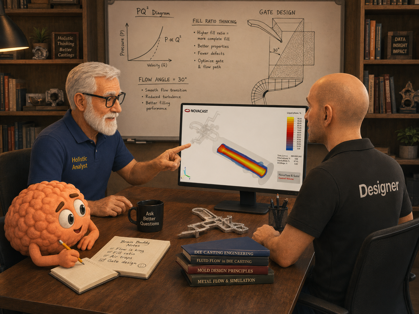
Part 2
Part Two — Gating, Porosity, Surface Treatments & Design for Manufacture
The finish on your die cast part does not tell you the truth. The naked casting does. Part Two picks up where the production journey ends and goes deeper into the decisions that follow — the gating system and what it means for weld lines and flow quality, porosity and its roots in design choices, and why every designer should see the as-cast shot before any plating or coating is applied. It also covers the metallurgical consequences of surface treatment specifications, what shot ratio and melt condition mean for part integrity, and how to design for the secondary operations that follow casting. Part of the Combating Engineering Mindblindness series.
Part 2 Audiobook → https://www.dropbox.com/scl/fi/b4i0uislu4968c14gsdmh/Designer_Journey_HPDC_part2_McFadden_7May2026.mp3?rlkey=rvpbn09tub1vhk33m9qoungz3&st=f60re4ju&dl=0
COMBATING ENGINEERING MINDBLINDNESS SERIES
HIGH PRESSURE
DIE CASTING
What Every Designer Needs to Know
PART TWO
Gating, Porosity, Surface Treatments & Design for Manufacture
Joseph P. McFadden Sr.
Engineering Fellow, Zebra Technologies
Adjunct Professor of Mechanical Engineering, Fairfield University
Collaboratively developed with Claude · May 2026
mcfadden@snet.net · www.MCFADDENCAE.com
If you are joining us here directly, the series is built on a simple premise: engineers who can see beyond the boundaries of their own discipline make fewer mistakes, ask better questions, and design better products. Mindblindness is not a character flaw — it is a gap in exposure. This series closes those gaps.
In Part One we covered what die casting is, the difference between cold and hot chamber machines, the three main alloys and what they mean for your design choices, and the complete journey from furnace to ejected part — told through the lens of your decisions as a designer.
If you have not listened to Part One, I recommend starting there. What we cover in this part builds directly on that foundation.
Welcome back.
In Part One we covered what die casting is, the difference between cold and hot chamber machines, the three main alloys and what they mean for your design, and the complete journey from furnace to ejected part — translated into terms that connect to your decisions as a designer.
Now we go deeper. We are going to talk about the gating system — because understanding where and how metal enters your part is one of the most valuable pieces of knowledge a designer can have. We are going to talk about porosity, what causes it, and how your design decisions either create it or prevent it. And we are going to talk about surface treatments — because the specification you write on your drawing for plating or anodizing or painting is not just a finish decision. It has metallurgical consequences that can cause your part to fail in service, invisibly, long after it left the factory.
All of it connects. That is the holistic approach.
THE GATING SYSTEM — WHAT IT IS AND WHY IT MATTERS TO YOU
When a die cast part is ejected from the machine, it is not just the part. It is the part plus a network of solidified metal attached to it — runners, gates, and overflow wells. That entire assembly gets separated at the trim operation, and what is left are the gate marks on your part.
Most designers think of the gating system as a production detail — something the tooling engineer handles, nothing to do with them. That is a mistake. The gating system is one of the most consequential decisions in the entire die casting process, and your part geometry is what drives it.
Let me explain what it is, and then explain why you should care.
The gating system is the path the metal takes from the shot sleeve — the cylinder where the metal is injected — to your part cavity. It consists of: the sprue or biscuit, which is the initial slug of metal at the injection end; the runners, which are channels that distribute metal toward the cavity; the ingates, which are the final restrictions through which metal enters your part; and the overflows, which are small reservoirs on the far side of the cavity that collect the first, coldest, most contaminated metal.
Each element serves a purpose. The runners deliver metal without losing too much temperature or pressure. The ingates control the velocity and direction of metal entering the cavity. The overflows ensure the first metal through — which carried air and lubricant vapors and oxide films — exits the part rather than being trapped inside it.
WHERE THE GATE GOES AND WHY IT MATTERS
The ingate is the most critical element. Its location on your part determines the entire fill pattern — the path the metal takes as it sweeps through the cavity. And that fill pattern determines everything: where weld lines form, where porosity concentrates, where surface quality is best and worst, and where the mark is left after trimming.
A weld line — sometimes called a cold shut — is where two separate flow fronts meet inside the cavity and must fuse together. If both fronts are hot enough and moving fast enough when they meet, they fuse cleanly. If one front has lost too much temperature before meeting the other, they do not fuse properly. The result is a visible line and a mechanical weakness at that location.
Weld lines are not a production defect in the traditional sense — they are a geometric inevitability for any part that has features which force the metal to split and rejoin. Your design determines where they form. The gating system determines whether they form in a high-stress area or a low-stress one.
As a designer, you should be asking: where is the gate going to be on my part? Where will the metal flow last? Are those last-to-fill areas in a location that matters mechanically or cosmetically? If the answer is yes, the design needs to change — not the tooling.
POROSITY — THE INVISIBLE DEFECT THAT IS PARTLY YOUR FAULT
Porosity is the presence of voids inside the casting — either gas voids or shrinkage voids. It is the most common die casting defect and the one most often blamed entirely on the foundry. In reality, the designer contributes to it in ways that are preventable.
Gas porosity comes from air and gas that gets trapped during fill. Air that does not escape through the vents before the metal arrives. Lubricant vapors that could not exit from deep pockets in the cavity. Hydrogen dissolved in the melt that comes out of solution during solidification.
Your design contributes to gas porosity when you create deep blind pockets that are hard to spray and vent. When you create geometries that cause the metal to fold over itself during fill — trapping air inside the fold. When you specify alloys or surface treatments that introduce hydrogen into the metal.
Shrinkage porosity comes from the six percent volume loss that aluminum undergoes as it solidifies. Metal cannot shrink into empty space — something has to fill that void. In a well-designed part with a well-designed gate, the intensification pressure feeds additional metal through the still-open gate to compensate for shrinkage. In a poorly designed part, the gate freezes before the thick sections solidify, and the shrinkage creates voids in the interior.
Your design contributes to shrinkage porosity when you create thick sections — bosses that are too heavy, walls that vary dramatically in thickness, transitions that are too abrupt. The thick section solidifies last. By the time it needs to shrink, the surrounding thinner sections have already frozen and locked the thick section in. The shrinkage has nowhere to go but inward — forming voids.
Porosity is not always visible from the outside. That is what makes it dangerous. A part can look perfect, pass dimensional inspection, and still be full of internal voids that reduce fatigue life, create leak paths, and cause failure under loads that should be well within the design margin.
X-ray inspection can reveal internal porosity. Leak testing can reveal through-connected voids. But the most effective way to manage porosity is to design the part so that it is minimized from the start — uniform walls, no abrupt section changes, no deep pockets, draft on all surfaces.
WHAT GOOD FLOW LOOKS LIKE — AND HOW YOUR DESIGN ENABLES IT
Here is a way to visualize what the tooling engineer is trying to achieve with the gating system, and how your design either helps or fights that goal.
Imagine filling a room with water from a single inlet in one wall. If the room is a simple rectangle with an outlet vent on the opposite wall, the water fills smoothly from one side to the other — a clean, sweeping front.
Now put obstacles in the room. Pillars, dividing walls, raised floors, odd-shaped recesses. The water has to split around obstacles, rejoin on the other side, swirl into recesses, race through narrow passages and spread in open ones. Air gets trapped in corners the water cannot reach until late in the fill. Some areas fill before others.
Your die casting cavity is that room. The metal is the water. The goal of the gating system is to place the inlet — and design the runner system leading to it — so that the fill front sweeps through the cavity as cleanly as possible, pushing air ahead of it toward the vents and overflows.
Features that help: uniform wall thickness so the metal advances at consistent speed everywhere. Smooth transitions between sections. Generous radii so the metal can follow the geometry without separating from the wall. Well-placed overflow wells in the last-to-fill areas so the cold, oxide-laden metal that arrives there exits into the overflow rather than staying in the part.
Features that hurt: abrupt changes in wall thickness that cause the metal to race through one area and struggle in another. Sharp corners that cause turbulence. Deep pockets that trap gas. Complex geometries that force multiple flow fronts to meet in structurally critical locations.
READ THE CASTING BEFORE YOU COVER IT
There is a principle I come back to in nearly every failure investigation I have ever done, and I want to share it with you before we talk about surface treatments.
I call it lipstick on a pig.
No amount of chrome plating, anodizing, powder coat, or paint changes what is underneath. The surface treatment covers the casting — it does not improve it. If the casting has problems, those problems are still there after plating. Often they are worse, because the plating process itself can introduce new defects on top of the existing ones. And the finish covers everything so completely that by the time the part reaches you as a designer, or reaches the field as a product, you cannot see what is actually going on.
This is why I believe every designer who specifies a die cast part should see the as-cast shot before any secondary operations are performed. Not just the part — the complete shot. The part, the runner system, the gate, the overflows, all still attached. The casting in its natural state. Its birthday suit.
That complete assembly tells you things that the finished, plated part will never reveal.
Look at the flow patterns on the surface. Where the metal flowed smoothly, the surface will be even and consistent. Where flow fronts met and struggled to fuse, you will see flow lines — subtle ripples or texture changes that follow the fill pattern. Where turbulence occurred, the surface may show swirl marks or irregular texture. Where gas was trapped and then partly escaped, you may see small depressions or blisters. All of this is visible in the as-cast state. Almost none of it is visible after plating.
Look at the discoloration. Areas that ran hotter, areas where the die spray pooled and burned, areas where the metal velocity was too high — all of these leave thermal signatures on the as-cast surface. A yellowish or brownish tinge in a specific area is the casting telling you something about what happened there during fill. A bright, almost mirror-like area at the gate region tells you the metal arrived hot and fast. A dull, grainy texture in a last-to-fill corner tells you the metal was cold and struggling when it got there.
Look at the overflows. The overflow wells collected the first, coldest, most contaminated metal that entered the cavity. If those overflows look dark, grainy, or show evidence of oxide inclusions, that tells you about the melt quality going into the part. If the overflows are clean and consistent, that is a good sign. If they are irregular or show evidence of turbulence, that turbulence happened in your part too before the metal reached the overflows.
Look at the gate area. The gate is where the metal entered at the highest velocity and temperature. It is often the cleanest area of the casting for that reason. But if you see erosion marks, or a rough, torn surface at the gate, that tells you the velocity was too high and the gate is eroding the die steel — a problem that will worsen over the life of the tool.
Look at the parting line. The flash — the thin fin of metal that forms where the die halves meet — tells you about clamping force and die fit. Excessive flash means the die is opening under injection pressure, or the die faces are wearing. A slight, consistent flash is normal and trimmable. An irregular or heavy flash is a warning.
All of these blemishes, discolorations, and surface patterns are preludes. They are the casting telling you what happened during its formation — and what may happen to it in service. A flow line in a cosmetically irrelevant area may be acceptable. The same flow line across a stress-critical feature is a failure waiting to happen. You cannot make that judgment if you have never seen the part in its natural state.
Now — and this is the equally important second half — the secondary operations you specify can introduce their own defects on top of whatever the casting arrived with.
The acid pickling step in electroplating attacks the surface. If there are pores or micro-cracks at the surface, the acid enters them, widens them, and the plating then seals them in with whatever contamination the acid left behind. The anodizing process creates a hard oxide layer more brittle than the base aluminum — in a part with residual surface tension, that brittle layer can crack. Shot blasting for pre-treatment work-hardens the surface and can drive existing surface defects deeper.
So you have two separate phenomena to understand: the defects the casting brings to the finishing line, and the defects the finishing process adds. The as-cast part shows you the first set clearly. The finished part hides both sets behind its surface. This is why failure analysis on plated castings is so difficult — you are often peeling back layer after layer of processing history before you find the original source of the problem.
Ask to see the as-cast shot. Ask your foundry to show you the part before it goes to finishing. Make it a standard part of your first article review. The five minutes you spend looking at the naked casting may save you months of failure investigation later.
SURFACE TREATMENTS — THE DECISIONS THAT FOLLOW YOUR CASTING
Electroplating — chrome, nickel, copper — requires the part to go through an acid pickling bath before the metal can be deposited. That acid bath cleans the surface so the coating will adhere. It does that job. But in doing that job, it also generates hydrogen at the metal surface. Atomic hydrogen. Small enough to slip between the atoms of the metal lattice and diffuse inward.
Once inside the metal, that hydrogen migrates. It finds grain boundaries, pores, and areas of high stress — exactly where it does the most damage. Then the plating goes on, and it seals the hydrogen in.
The result is a part that looks perfect. That measures perfect. That passes inspection. And that, days or weeks or months later, fractures. Brittle. Sudden. Without the kind of plastic deformation you would expect before failure.
This is hydrogen embrittlement. And it disproportionately affects die castings because of the residual tension in the core we talked about earlier, combined with the porosity that provides pathways for hydrogen to migrate, combined with the thin walls that have very little material to absorb the effect before it reaches a critical location.
The bake-out treatment — heating parts to around one hundred and ninety degrees Celsius for several hours immediately after plating — drives out mobile hydrogen before it has time to concentrate at grain boundaries. The word immediately matters here. The window for effective bake-out narrows rapidly after plating. Hydrogen that has had time to migrate to grain boundaries and form molecular hydrogen in micro-voids cannot be removed by baking.
As a designer, if you are specifying electroplating on a die cast aluminum or zinc part, you need to understand this mechanism and build the bake-out requirement into your specification. And you need to understand that parts with internal porosity — which provides additional hydrogen migration pathways — are at significantly higher risk. This loops back to wall thickness, section design, and everything else we discussed.
Anodizing is an alternative surface treatment for aluminum that does not involve the same degree of hydrogen risk. It is an electrochemical oxidation process that builds up a protective oxide layer on the surface. However, not all aluminum die casting alloys anodize equally well — the high silicon content of alloys like A380 produces a mottled or gray finish. If you want a consistent, attractive anodized finish, your material specification matters.
Powder coat and liquid paint are much more forgiving of surface condition and are not associated with hydrogen embrittlement. If your plating specification is driven by aesthetics rather than by a functional requirement — conductivity, solderability, wear resistance — paint or powder coat may be the right answer, and the risk profile is completely different.
Conversion coatings — chromate or non-chromate — provide basic corrosion protection for aluminum and magnesium with minimal processing risk. They are often used as a base coat under paint or powder coat.
The surface finish decision is not just about appearance. It is a materials decision with mechanical consequences. Make it with full knowledge of what it does to the metal underneath.
DESIGNING FOR SECONDARY OPERATIONS
Most die castings need at least some secondary work before they are finished. Understanding what those operations are and how to design for them saves time and cost.
Machining. Features that require tighter tolerances than the casting process can hold — precision bores, sealing surfaces, mating faces — are machined after casting. The casting provides a near-net-shape blank that the machining operation finishes. Design these features with adequate stock for the machining pass. Typically one to one and a half millimeters of stock on diameter for a bored hole. Allow fixturing pads — flat surfaces where the machining fixture can clamp the part without marring a finished surface.
Tapping and threading. Die cast aluminum is soft enough to accept self-tapping screws in many applications — particularly for light, non-structural assemblies. For structural connections, thread-forming taps into a properly sized cast hole work well. For high-load applications with repeated assembly and disassembly, threaded inserts — installed by pressing or casting-in — are the right answer. Specifying a thread directly into a thin-walled boss that will see fastener torques is how warranty claims get generated.
Trimming and deburring. The gate, runner, and overflow marks must be removed. Depending on the geometry, this is done in a trim die, by hand grinding, or in a tumbling operation. Design the gate location so the trim operation does not leave witness marks in cosmetically critical or mechanically critical areas. Allow clearance around the gate location for the trim tooling.
TALKING TO THE FOUNDRY — WHAT EVERY DESIGNER SHOULD DO
Here is a piece of advice that goes beyond the technical content of this guide.
Talk to the foundry early.
Before the design is released. Before the die is ordered. Ideally, before the design is finalized.
The people on the production floor — the tooling engineer, the process engineer, the quality engineer — have knowledge that no design guideline document captures. They know which features in your design are going to be difficult to fill. They know where the parting line will have to go and what that means for your tolerances. They know whether the draft on a particular feature is adequate or whether it is going to cause them problems in ten thousand cycles.
Most designers never visit the production floor. They release drawings, receive first articles, and then deal with problems. The designers who prevent problems — the ones who build a reputation for parts that run cleanly and do not generate warranty claims — are the ones who understand the process well enough to have a real conversation with the foundry.
This guide is a starting point for that conversation. It is not a substitute for it.
THE COMPLETE PICTURE
Let me bring it all together for you.
Your die cast part begins as a liquid metal bath in a furnace, where its hydrogen content is being managed — or mismanaged. It is delivered as a precisely measured shot into a cold shot sleeve, where the clock starts. It is pushed through the die in two phases: a slow, controlled advance to avoid air entrapment, and a fast, high-velocity fill that takes milliseconds. It is pressurized after filling to feed shrinkage. It solidifies with stresses locked in from the outside in. It is ejected, degated, and inspected. Then it goes through surface treatment that can introduce new failure mechanisms if not specified and controlled correctly.
Every step of that journey was influenced by decisions you made on your drawing.
Wall thickness. Draft angles. Rib geometry. Boss design. Parting line placement. Surface finish specification. Material selection. Tolerance call-outs.
None of these are isolated decisions. They are all connected. They all affect each other. And they all trace back to physics — the behavior of liquid metal moving at high speed through a precision steel cavity under enormous pressure, transitioning from liquid to solid in a fraction of a second.
When you understand that physics — even at the level we have covered here — your design decisions change. You stop asking "can we make an exception to the draft requirement" because you understand why it is not an arbitrary rule. You stop specifying electroplating on thin-walled aluminum parts without thinking about hydrogen embrittlement because you understand the mechanism. You stop designing thick sections without realizing they are creating porosity hot spots.
Understanding the complete journey is not optional. It is the whole point.
I have said that twice now — once at the start and once here at the end. I mean it both times.
Every failure tells a story. With what you have learned here, you are better equipped to write a different kind of story from the start. A part designed with the process in mind. A casting that arrives at the field with a good history inside it — not one full of voids and residual hydrogen and stress concentrators waiting for the right moment to cause a problem.
I would rather help you write the positive story. That is why this guide exists.
Thank you for listening.
Joseph P. McFadden Sr. Engineering Fellow, Zebra Technologies. Adjunct Professor of Mechanical Engineering, Fairfield University.
You can reach me at mcfadden@snet.net. My blog is at www dot MCFADDENCAE dot com.
My companion guide — Die Casting Metallurgy, A Comprehensive Guide — covers hydrogen embrittlement, plating effects, stress corrosion cracking, and materials science fundamentals in depth. It is available free at the same address.

Part 2
Part 2 — Die Meets Machine This is where the math and the metal shake hands. PQ² analysis — the engineering handshake between your die design and the machine's capability — tells you whether what you designed will actually run. We cover fan and tangential runner design, overflow sizing, vent area calculation, vacuum systems, freeze blocks, and simulation strategy. There's also an expanded section on modern AI-assisted defect prediction, building on the foundation Mike Ward established in the original NADCA Gating Manual.
Audiobook part 2 → https://www.dropbox.com/scl/fi/b2giplw3cuud162zt4n36/Pro_Version_Part_2_Journey_HPDC_Journey_8_May2026.mp3?rlkey=myvussw44ozyiuo03bwgq34qu&st=pdfui0jh&dl=0
HIGH PRESSURE DIE CASTING
HPDC Gating: A Holistic Journey
PART TWO · PROFESSIONAL EDITION
PQ² Analysis · Runner & Gate Design · Simulation · Defect Prediction
Joseph P. McFadden Sr.
Engineering Fellow, Zebra Technologies
Adjunct Professor of Mechanical Engineering, Fairfield University
44+ Years · Manufacturing Simulation & Failure Analysis
Collaboratively developed with Claude · May 2026
mcfadden@snet.net · www.MCFADDENCAE.com
Now we bring it all together. This is where the die meets the machine. Where the mathematics of PQ squared analysis tells you whether what you designed will actually work on the equipment you have. Where runner geometry and overflow placement turn theory into metal in motion. And where simulation lets you see the fill before you commit to steel.
Let's continue.
Chapter 6: PQ² Analysis — Matching Die to Machine
You now have your ingate areas, velocities, and flow rates calculated. The next critical question is simple but decisive: can the die casting machine actually deliver what you just designed?
This is where PQ² analysis comes in. It is the engineering handshake between the die and the machine. P stands for metal pressure. Q stands for metal flow rate. The squared term comes from the physics — flow rate and pressure are not linearly related.
Stand next to a die casting machine during a shot and you will feel this relationship in your bones. When the accumulator fires, you hear a deep hydraulic thud. The plunger surges forward. If the gating system is too restrictive, the pressure spikes sharply and the machine strains. If the gates and runners are too open, the machine cannot build enough pressure and the cavity does not fill completely before the metal starts to freeze. PQ² analysis lets you predict and balance that behavior on paper before steel is ever cut.
The Physics Behind It — Bernoulli's Equation. Molten metal flowing through the narrow ingate behaves like any fluid moving through an orifice. The governing relationship comes from Bernoulli's principle: metal pressure is proportional to the square of the flow rate, divided by the square of the ingate area, adjusted by a few constants and the efficiency of the system. In plain terms: push more metal per second — higher flow rate — and you need much higher pressure. Make the ingate smaller and pressure requirements rise sharply. Improve system efficiency with smoother runners and better plunger fit and you need less pressure for the same flow. This non-linear relationship is why small changes in gate thickness or plunger diameter can make a surprisingly large difference on the shop floor.
The PQ² Graph — Your Visual Operating Window. Engineers use special graph paper, or software, where the horizontal axis is Q squared — flow squared — and the vertical axis is pressure. This makes the curved physics appear as straight lines, which are much easier to read.
The Machine Performance Line shows everything the machine can deliver at your chosen accumulator pressure and plunger diameter. One end shows maximum pressure at zero flow — the machine is stalled against a blocked die. The other end shows maximum possible flow at zero pressure — dry shot speed with nothing to push against. This line represents what the machine can physically deliver.
The Die Resistance Line is calculated from your ingate area, chosen velocity, and Bernoulli's equation. It shows what the die demands in order to receive that exact flow rate.
Where these two lines intersect is your actual working point. Now draw two important boundaries: a vertical line for minimum flow rate based on your target cavity fill time — everything must be to the right of this line or the cavity will not fill in time — and a horizontal line for minimum pressure based on your chosen ingate thickness and intensification needs. Everything must stay above this line.
The box created in the middle is your safe operating window. A large, comfortable window means the process will be stable even when conditions vary — temperature fluctuations, minor changes in metal viscosity, normal die wear. A tiny or nonexistent window means you will be fighting the machine on every shift.
What Changing Parameters Looks Like on the Floor. A smaller plunger tip steepens the Machine Performance Line — more pressure available, but less total flow. You feel the machine working harder, delivering precise control on smaller or thinner parts. A larger plunger tip flattens the line — more flow, but lower pressure — good for big castings that need volume more than squeeze pressure. Higher accumulator pressure shifts the line upward in parallel, adding power across the board. A larger ingate area flattens the Die Resistance Line, making flow easier but potentially losing velocity and fill quality.
Experienced process engineers walk up to a machine, look at the current settings, and can often tell just from the sound and the way the die fills whether it is operating near the center of its window or right on the edge.
Practical Goal. Your target is a generous operating window that comfortably meets your required fill time, ingate velocity, and intensification pressure — all while staying well within the machine's safe limits. This is the point where the die and the machine are truly working together instead of fighting each other.
When this analysis is done correctly, your first shots on the new die land very close to the predicted parameters. When it is skipped or done poorly, you spend weeks chasing adjustments on the shop floor, burning through metal, time, and die life.
Chapter 7: Designing Fans and Tangential Runners — The Art of Metal Delivery
You have defined the ingates. Now it is time to design the runners that feed them. This is where the metal's journey turns from calculation back into physical reality inside the die steel.
Always design the runner system backwards — starting at the ingate and working toward the biscuit or sprue. This ensures the gate remains the smallest, most restrictive point in the entire flow path. If any part of the runner is smaller than the gate, it steals control from where you want it.
Stand in front of a sectioned die on the toolmaker's bench and you can see exactly what this means. The runner channel is noticeably larger than the ingate. As it approaches the gate, the cross-section tapers down smoothly. This gradual restriction keeps the runner full of solid metal right up to the gate, pushes out air and lubricant vapors ahead of the flow, and delivers a clean, pressurized stream into the cavity.
Runner-to-Gate Area Ratio. The runner cross-section is typically one point one to one point four times larger than the ingate area for aluminum. Smaller ratios — one point one to one point two — work for modest flow angles. Larger ratios up to one point four are needed when the metal enters the cavity at steeper angles, greater than ten to fifteen degrees, to force it to spread properly across the full gate width. For zinc use tighter ratios, often one point zero five to one point one five, because the gates and runners are smaller and the metal flows faster. Magnesium can tolerate slightly larger runners and higher velocities to compensate for its lower heat content.
On the shop floor you will notice the difference: a properly sized runner gives smooth, consistent shots. One that is too large wastes metal and pressure. One that is too small causes turbulence and cold metal reaching the gate.
Two Main Runner Styles.
Fan Runners. Fans spread metal outward from a central point, creating a strong, even fill — like opening a garden hose nozzle from a tight stream into a wide, controlled spray.
Straight-sided fans are easier to machine and break cleanly at the trim press. However, the metal tends to jet more at the edges, pulling in extra air and creating porosity. You will often see more surface swirls on parts gated this way.
Curved-sided fans force the metal to follow the fan shape more naturally, reducing turbulence and delivering a smoother front into the cavity. They machine cleanly into the die but usually require a trim die because the gate does not break as sharply. On high-quality surface parts, the reduced gas entrapment is worth the extra trimming step. When you look at a curved fan in a die, notice how the sides gently curve outward — this geometry keeps the metal pressed against the walls instead of breaking away and folding air into the flow.
Tangential Runners. These bring metal in along the edge of the casting rather than straight on. They are excellent for long, rectangular, or irregularly shaped parts. The metal flows parallel to the edge before turning into the cavity, giving more distance for the flow front to develop and spread.
A good tangential runner includes a small shock absorber at the far end — a short, widened pocket that is about ten percent of the runner's inlet area. Without it, the advancing metal can spurt violently into the cavity at the very end of the runner, eroding the die steel over thousands of shots and creating a jet that traps air. With the shock absorber, the runner fills completely first, then feeds the gate smoothly. You can actually hear the difference in shot consistency on the machine.
Practical Design Details. Ramps from runner to ingate are usually sloped about five degrees. This gentle transition prevents turbulence. For irregular casting edges, you can angle the tangential runner or extend the ramp to direct flow exactly where you need it. Curved fans often have varying flow angles from left to center to right — when calculating actual ingate area, use the average angle: left plus right divided by four, plus center divided by two.
On the toolmaker's bench or in simulation, trace the metal path with your finger. The runner should guide the metal like a well-designed highway on-ramp — no sudden turns, no bottlenecks, and a controlled merge into the cavity. When this geometry is right, the first shots on the new die fill cleanly with minimal adjustments. When it is wrong, you will spend days welding, grinding, and recutting steel while production waits.
This is the art inside the engineering. The calculations give you the sizes. The experience and visualization give you the shape that makes the metal behave. Get the runners right, and the ingates can do their job exactly as designed.
Chapter 8: Designing Overflows and Vents - The Air’s Escape Route
Overflows collect the initial contaminated metal that traverses the cavity, provide local heat to the far side of the cavity, and provide a base to help eject the casting off the die.
The number and size of overflows is a function of flow distance through the cavity. A good surface quality will have more overflows than commercial finish. Think of overflows as quality insurance they capture the first metal through, which carries air, lubricant, and oxide films.
Overflow Sizing
A guide to overflow size as a percent of the adjacent segment:
For very thin walls around point zero three three inches with fast fill times of point zero one two to point zero two one seconds: hardware quality needs 150 percent overflow, some cold shut allowed needs 75 percent.
For thin walls around point zero five inches with fill times of point zero one seven to point zero two nine seconds: hardware quality needs 100 percent, commercial allows 50 percent.
For medium walls around point zero seven five inches with fill times of point zero two six to point zero four four seconds: hardware quality needs 50 percent, commercial allows 25 percent.
For thick walls over point one inch, overflow percentages decrease.
Note: These values are typical values which may change for specific situations.
Overflow Placement
Overflows that connect to vents should be located at the last position of the segment to fill. If the overflow fills before the segment, backfilling will occur causing poor fill and porosity. Metal will be drawn to the outgates of distributed flow within the casting.
Like runners, overflows don’t get shipped, so the number and placement of overflows should be judicious.
Outgates
The outgate connects the casting to the overflow. The sum total of all outgate areas should be approximately one half the total ingate area, since outgates provide the passageway for air to escape through vents.
For aluminum, minimum outgate thickness is point zero two zero inches. For magnesium and zinc, minimum is point zero one zero inches. The outgate is the choke point for air.
Vents
Vents are essential to die casting. Vents let air out of the die during the shot. If this doesn’t happen, air and other gases will be trapped within the metal. These bubbles can be concentrated in areas that were last to fill or in the form of smooth round bubbles forming gas porosity.
There’s a big difference in residual air and resultant casting quality between no vents and proper vents If the die is designed with insufficient vents, over time flash will be crushed around the perimeter of cavity inserts causing continuous flash or “natural venting.” This all can be avoided by designing proper vents.
Vent Area Calculation
Another way to determine vent area is dividing ingate area by four:
Vent Area equals Ingate Area divided by 4.
Since the normal range of ingate velocities is less than 2000 inches per second, this formula can also be used:
Minimum Vent Area equals flow rate Q divided by 8000.
The problem in designing a venting system with proper area is finding real estate on the die to put all the vents in. It’s always a good idea to have a plan for vents before signing off on cavity insert sizes.
Sometimes the cavity is in the ejector die, the ingates are in the cover die, and the vents are in the ejector die. The vent can be machined into cavity insert steel and polished so cast metal doesn’t stick to them.
Vent Design
Vent thickness varies from point zero zero five to point zero two zero inches. Air has less resistance flowing through vents that are point zero two zero versus ones that are thinner. It’s a good idea to machine a small radius between cavity and vent to help pull the vent off the die upon ejection.
Some vents are designed with steps to pull the vent off the die. For example, vent thickness starts at point zero two zero, then goes to point zero one five, and finally to point zero one zero.
Vacuum Systems
A better system than vents to remove air is evacuating the die during the shot with a vacuum system. Vacuum removes air and also lowers pressure on metal, making it easier to fill the die.
Vacuum has a few disadvantages. The vacuum channels need to be large enough with low resistance to handle airflow during evacuation for the system to work properly. The time available for the vacuum system to work is less than 1 second. Although pressure from incoming metal will push some air out, the vacuum system should have evacuated most air before metal arrives.
The vacuum valve pulls vacuum throughout the entire shot including fast shot. What triggers the valve to close is metal itself reaching the valve. The valve is prone to failing as metal eventually blocks the system.
Freeze Blocks
The freeze block allows for large vent area in a small die area. The freeze block is a specially designed insert that creates a large venting surface. Metal flows into the freeze block but freezes quickly due to high thermal conductivity, sealing the vent before significant metal loss occurs.
The freeze block needs to be sprayed with air and die lube to prevent metal fragments from sticking and building up on the freeze block.
Chapter 9: Simulation - Seeing Before Building
The use of simulation is certain to become more popular as computers become more powerful and simulation software capability gets better. Simulation is a useful engineering tool and should be used to supplement the engineering work of gating, not to replace it.
In the described gating process in this manual, there are a lot of assumptions made by the designer and in the techniques described. Simulation should be done after the gating design is complete. Using simulation has several useful and important objectives that can assist making the gating design better.
Five Key Questions for Simulation
First: What does the simulator say about the flow pattern? Is the flow pattern similar to one envisioned in Step 2?
Second: Where are the last areas to fill? Are the outgates adjacent to these areas?
Third: Are there areas of trapped gas critical to porosity control? Does the proposed design and pattern address them?
Fourth: Does shrink porosity occur in areas critical to porosity control? Does the proposed ingate location and thickness address them?
Fifth: Is there strong flow to areas where surface finish matters?
Last to Fill
The last areas to fill is the easiest and probably most important of the factors located by the first simulation run. There may be several pockets of possible trapped gas where gas has no escape path and is surrounded by liquid metal at end of fill. These locations could have gas porosity and perhaps poor fill.
A product of NADCA research efforts is a program called CastView, designed to locate the last point to fill quickly. The program can run in minutes as opposed to hours needed by full-blown commercial simulation software. It also can be run by anyone and doesn’t need a trained simulation operator to use it.
The designer should determine if these last areas are acceptable or not. If not, the gate can be relocated or added. If they’re in areas where surface finish or porosity matters, then possibly flow patterns with revised ingate locations can be changed and another simulation done.
Trapped Gas
If there are areas of trapped gas critical to porosity control, the gating can be changed to eliminate the trap or an overflow added. If the trapped gas is in the center of a thick section, it may not be a problem as long as porosity is contained within the section.
Shrink Porosity
If there is concern about shrink porosity, then an initial thermal analysis should be run. The thermal analysis will be needed for oil and water cooling channel placement and can predict the cold areas and hot areas that may affect surface finish or shrink porosity.
Most systems at this time cannot predict the cold areas and hot areas accurately, but they give valuable guidance on where problems might occur.
Computers are getting faster and software is getting cheaper and better. The days are coming where simulation will be the standard method of verifying and optimizing gating designs.
Added Section: Modern Defect Prediction Methods A word before we begin this section: these tools do not replace engineering judgment. They amplify it. The best simulation in the world, combined with the best machine learning algorithm, still needs an engineer who understands the metal's journey to interpret what it is showing.
Now let’s talk about something Mike Ward couldn’t have fully anticipated when he wrote the original manual: how artificial intelligence and machine learning are revolutionizing defect prediction in die casting
The Evolution of Defect Prediction
Defect prediction has evolved from empirical rules to advanced computational and AI tools. According to the NADCA Gating Manual, defects like porosity are tied to quality requirements defined early in design. But now we can go further.
Die casting is a high-pressure manufacturing process where molten metal is injected into a mold to form complex parts. Defects can occur due to improper gating, process parameters, or material issues. Predicting these defects is crucial for reducing scrap rates, which can reach 5 to 10 percent in production without proper controls.
Key Defects: The Usual Suspects
Let me describe the main defects you’ll encounter:
Porosity: Voids caused by trapped gas from air, lubricants, or hydrogen, or shrinkage during solidification. Gas porosity appears as round holes. Shrink porosity is irregular and occurs in thick sections. Think of gas porosity as air saying “you didn’t let me escape” and shrink porosity as metal saying “you didn’t feed me with pressure.”
Cold Shuts: Surface lines or cracks where metal flows meet but don’t fuse properly due to premature cooling. These are the scars where two metal streams greeted each other but were already too cold to shake hands.
Shrinkage: Cavities from metal contraction, often in hot spots or last-to-solidify areas. This is the 6 percent volume loss as metal goes from liquid to solid finding expression in voids.
Surface Defects: Like flow marks, blisters, or inclusions from turbulence or contamination. These are the visible storytellers of what went wrong during the shot.
These can lead to leaks, weak mechanical properties, or aesthetic issues in parts for automotive, electronics, or aerospace applications.
Alloy-Specific Examples
Defects vary by alloy due to differences in properties like density, melting point, fluidity, and susceptibility to gases or shrinkage.
Aluminum alloys like A380 and A356 are prone to hydrogen-induced gas porosity due to moisture absorption, leading to pinholes or blisters. Shrink porosity often occurs in thick sections like engine blocks. Examples include round voids in automotive transmission housings from trapped hydrogen or air, predicted via venting simulations. Irregular cavities in structural brackets, mitigated by proper ingate placement near hot spots. Visible lines on thin-walled electronics enclosures from slow fill times. Cracks in complex geometries like wheel rims due to thermal stresses during solidification.
Zinc alloys like Zamak 3 and Zamak 5 have excellent fluidity but are susceptible to surface defects like flow marks from rapid cooling. Blisters from trapped gas are common in decorative parts. Examples include streaks on hardware fittings like door handles from uneven metal flow, prevented by optimized gate velocity. Bubbles on plated components like locks, caused by subsurface gas expansion during heat treatment. Depressions on thin sections of consumer electronics housings from shrinkage. Metal sticking to the die in high-volume production of fasteners, leading to drag marks.
Magnesium alloys like AZ91D and AM60B have low density but high shrinkage rates and oxidation sensitivity, often resulting in porosity bands or hot tears in lightweight automotive parts. Examples include cavities in steering wheel frames from rapid cooling and low latent heat, simulated for prediction. Pores in laptop chassis from trapped air or SF6 cover gas reactions. Cracks in thin-walled drone components due to high thermal contraction. Surface defects in engine covers from improper melt protection, appearing as rough spots.
These examples highlight how gating adjustments like higher velocities for magnesium can prevent alloy-specific issues, as per NADCA guidelines.
Method 1: Analytical Gating Design
Based on engineering calculations to prevent defects proactively. The NADCA manual outlines a 9-step process where quality specs guide parameters like ingate velocity and fill time to avoid turbulence or premature freezing.
Key factors for prediction:
For gas porosity from trapped air, steam, or hydrogen in aluminum: Ensure vents evacuate 70 to 100 percent of cavity air. Calculate vent area as ingate area divided by 4. Predict via flow pattern visualization to avoid backfills.
For shrink porosity from metal contraction in hot slash thick areas: Position ingates near hot spots for high-pressure feeding. Check ingate thickness to delay freezing.
For cold shuts and surface issues from slow fill or low velocity: Calculate max fill time based on wall thickness. Use flow angles to minimize swirls.
This method relies on spreadsheets for PQ² analysis, matching machine pressure slash flow to gate, and assumes defects if parameters exceed limits, like atomized flow at high velocities.
Method 2: Simulation-Based Prediction
Casting simulation software uses computational fluid dynamics and thermal modeling to virtually test designs, predicting defects before tooling. As per the manual’s Chapter 9, run simulations post-gating to validate flow, identify last-to-fill areas prone to porosity, and check for trapped gas or shrinkage.
Tools and capabilities from industry sources:
AnyCasting simulates filling slash solidification and predicts porosity via shrinkage models. Used for aluminum crankcases. Integrates machine learning for process tweaks.
ADSTEFAN detects turbulence, air entrapment, misruns, and optimizes gating. Used for high-pressure die casting for defect-free parts.
CastView from NADCA provides quick last-to-fill analysis in minutes and flags porosity risks. Supplements full simulations like MAGMASOFT or Novacast.
Simulations reduce iterations by 50 to 70 percent, predicting issues like blisters from gas or sinks from shrinkage. For high-pressure processes, vacuum-assisted simulations enhance accuracy.
Method 3: Machine Learning and Data-Driven Methods
This is where things get really interesting. Modern systems analyze process data like pressure, temperature, shot velocity to predict defects in real-time. These complement simulations for ongoing production.
Approaches include:
Random Forests and Neural Networks predict porosity from parameters like plunger speed, achieving accuracy up to 90 percent in hard disk drive components.
Support Vector Machines and Regression Trees diagnose causes like pre-heating issues and compare models for best fit.
Integrated Systems use IoT sensors for predictive maintenance. For example, a Korean system analyzes conditions to forecast defects.
The Holistic Integration
For best results, combine methods: Start with NADCA gating. Validate via simulation. Deploy machine learning for production monitoring. This can cut defects by 20 to 30 percent.
But here’s the holistic insight: these tools don’t replace understanding They augment it. The neural network can tell you porosity is likely, but it takes a human engineer who understands the metal’s biography to know why and how to fix it.
Machine learning is pattern recognition at scale. It’s seeing that every time shot velocity exceeds 120 inches per second with a gate thickness below point zero three inches and metal temperature below 1180 degrees, you get atomized flow and porosity. But it doesn’t understand why the way you do after reading this manual.
The simulation can show you where gas gets trapped. But it takes engineering judgment to decide whether to add an overflow, change the flow pattern, or accept the porosity because it’s in a non-critical area.
This is why I emphasize the holistic approach. Use the AI. Use the simulation. But understand the fundamentals Know why metal behaves the way it does. Treat the casting as a patient with a biography, not just a geometry to be filled.
Closing: The Conversation Continues
We’ve covered a lot of ground. From the basic principles of gating design to the cutting edge of AI-powered defect prediction. But remember at its core, die casting is about understanding how metal wants to flow and creating the conditions for it to flow well.
Good gating design is essential for making good parts and leads to successful die casting. Poor gating design makes poor parts and contributes to struggles in lowering scrap and meeting operational objectives.
The time invested in proper gating design yields higher quality castings and shop floor productivity. Every calculation, every simulation run, every thoughtful decision about gate placement these all contribute to that first shot success we’re chasing.
Remember the key principles:
Define quality requirements early and completely.
Visualize the flow pattern before calculating anything.
Design runners and gates working backwards from the cavity to the machine.
Match machine capabilities to flow requirements.
Check for atomization and adjust accordingly.
Provide adequate venting and overflows.
Use simulation to validate your design.
Apply modern data-driven methods to continuously improve.
But most importantly: think holistically. Understand that the die, the machine, the metal, and the process are all in conversation with each other. Your job as engineer is to facilitate that conversation toward success.
Thank you for listening.
If you have any questions or would like to discuss, my email address is,
McFadden @snet.net
My blog address is www.MCFADDENCAE.com
Thank you again, and have a wonderful day.
Joe McFadden.
REFERENCES AND FURTHER READING
The following works form the technical foundation of this guide or are recommended for further study. Where a referenced work is commercially published, readers are encouraged to obtain it directly. Discussion of published material does not imply affiliation with or endorsement by the original authors.
[1] Ward, M. NADCA Gating Manual for High Pressure Die Casting. North American Die Casting Association (NADCA). The primary technical foundation for Chapters 1–9 of this guide. Essential reading for any engineer involved in die casting process and tool design. Available through NADCA at www.diecasting.org.
[2] McFadden, J. P. (2026). Die Casting Metallurgy: A Comprehensive Guide — Embrittlement, Plating Effects, and Materials Science Fundamentals. Independent publication. A companion volume addressing hydrogen embrittlement, plating-induced failure, stress corrosion cracking, porosity, and residual stress in die cast parts in service. Covers aluminum, magnesium, and zinc alloys in depth. Free download at www.MCFADDENCAE.com.
[3] North American Die Casting Association (NADCA). Product Specification Standards for Die Castings. NADCA Publication C-8-2-06. Standard tolerances, surface finish classifications, and quality grading criteria referenced in Chapter 1. Also covers tooling standards and parting line specifications.
[4] NADCA EC-515 Die Casting Defects Course. North American Die Casting Association. Technical basis for the discussion of gas porosity sources, including the finding that plunger lubricant is the single largest lubricant-related source of gas porosity in die casting. Referenced in the plunger lubrication section of this guide.
[5] Yongzhu Casting Technical Bulletin (2025). Aluminum Die Casting Porosity: Complete Engineering Guide. Industry technical data source for shot sleeve fill ratio recommendations: minimum 50%, ideal 70–80% for aluminum cold chamber. Corroborates NADCA guidance on fill dynamics and turbulence thresholds.
[6] Verran, G. O., Mendes, R. P. K., & Rossi, M. A. (2006). The effect of porosity on the microstructure and mechanical properties of die cast magnesium alloys. SAE Technical Paper 2006-01-0524. Research basis for the discussion of filling ratio and shot sleeve temperature effects on AM50A magnesium alloy porosity. Confirms that sleeve temperature is the dominant variable in magnesium cold chamber processing — directly supporting the insulation and heater requirements of the hybrid cold chamber discussed in this guide.
[7] Chem-Trend Technical Report: How Plunger Lubricants Can Help. Chem-Trend L.P. Industry technical source on plunger lubrication best practices, consequences of over-lubrication including erratic shot profiles and gas porosity, and the role of worn plunger tips in driving excessive lubricant use. Referenced in the plunger lubrication diagnostic section.
[8] RYOEI EcoShot Technical Documentation. RYOEI Inc. Source for the Leidenfrost effect discussion in die spray evaluation — explaining why continuous spray on an overheated die causes lubricant to bounce rather than adhere, creating simultaneous over-lubrication in cool areas and under-lubrication in hot areas from the same spray program.
[9] Hill & Griffith Company Technical Bulletin: Die Casting Porosity — Lubricants, Blisters, and Shrinkage. Industry technical reference for the characterization of blistering as subsurface gas porosity, the mechanism by which the casting skin deforms at ejection temperature, and the cooling-based mitigation strategies.
[10] Brevick, J. R., & Klingler, L. J. (1996). CastView: A Program for Quick Estimation of Last-to-Fill Areas in Die Castings. NADCA Research Program. Background reference for rapid identification of last-to-fill locations prior to full CFD simulation. Discussed in context of Chapter 9 simulation methods.
[11] AnyCasting Co., Ltd. ANYCASTING Simulation Software for Die Casting. www.anycasting.com. CFD and thermal simulation platform referenced in the defect prediction and simulation chapters. Supports filling, solidification, and machine learning integration for process optimization.
[12] JSOL Corporation. ADSTEFAN Die Casting Simulation Software. www.jsol.co.jp. Simulation tool referenced for turbulence, air entrapment, and misrun prediction in high-pressure die casting. Used extensively in automotive and electronics applications.
[13] Yao, X., Shao, Z., & Ji, C. (2020). Application of Machine Learning in Defect Detection for High-Pressure Die Casting. Journal of Manufacturing Processes, 58, 1158–1167. Research basis for machine learning defect prediction methods discussed in the Modern Defect Prediction section, including random forest and neural network approaches achieving up to 90% prediction accuracy.
[14] The Federal Group USA. The Fundamentals of Hot Chamber Die Casting. Technical article confirming that magnesium is suitable for hot chamber die casting with appropriate shot sizing, and that hot chamber is the preferred architecture for magnesium when part volume permits. Cited in the machine architecture section.
[15] Street, A. C. (1977). The Die Casting Book. Portcullis Press, London. Foundational reference on die casting process fundamentals and historical context for gating system design evolution. Out of print but widely held in industry libraries.